EMISSION
AND
EVAPORATIVE LOSS CONTROL SYSTEMS
20
2-~
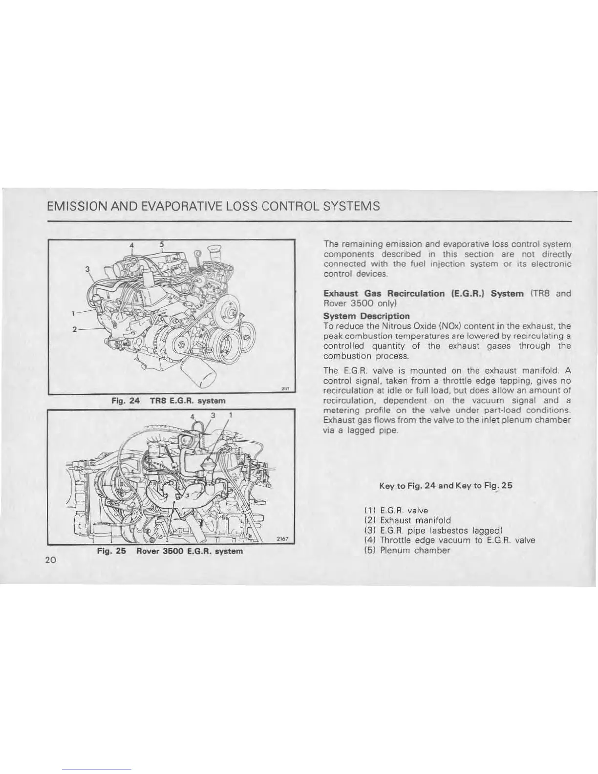
Fig.
24
TR8 E.G.R.
synem
Fig.
26
Rover
3500
e.G.R.
system
,.,
The
remaming emission and evaporauve loss control system
components
described in this section Bre
not
directly
connected With the fuel injection system or liS electronic
control devices
Exhaust
Gas
Recirculation
(E.G.R.)
System
(TAB and
Rover
3500
only)
System
Description
To reduce the Nitrous Oxide (NOx) content
in
the exhaust. the
peak combustion temperatures Bre lowered
by
recirculating a
controlled quantity of the exhaust gases through the
combustion process.
The
E,G.A.
valve is mounted on the exhaust manlfold. A
control signal, taken from a
thrallie
edge tapping, gives no
recirculation at idle or full load, but does
allow
an
amount
of
reCIrculation. dependent on the vacuum signal and a
metermg profile
on
the valve under part-load condilions.
Exhaust gas flows from the valve
to
the Inlet
plenum
chamber
via a lagged pipe
Key
to
Fig.
24
and Key
to
Fig;
25
(1)
E.G.A.
valve
(2) Exhaust manifold
(3)
E.G.A.
pipe (asbestos lagged)
(4)
Throttte edge vacuum
to
E.G.
A.
valve
(5) Plenum chamber