EMISSION
AND
EVAPORATIVE LOSS CONTROL SYSTEMS
To measure the air
flow
Into the engine an
Air
Flow
Meter
is
fitted
In
the engine
compartment
between the air cleaner and
a
plenum
chamber above the engine. The plenum chamber
acts
as
a
collecting
bOil:
for the mgolng air and helps
to
smooth
out
any rapId fluctuations in air
flow
that might upset
the
Air
Flow
Meter
signals.
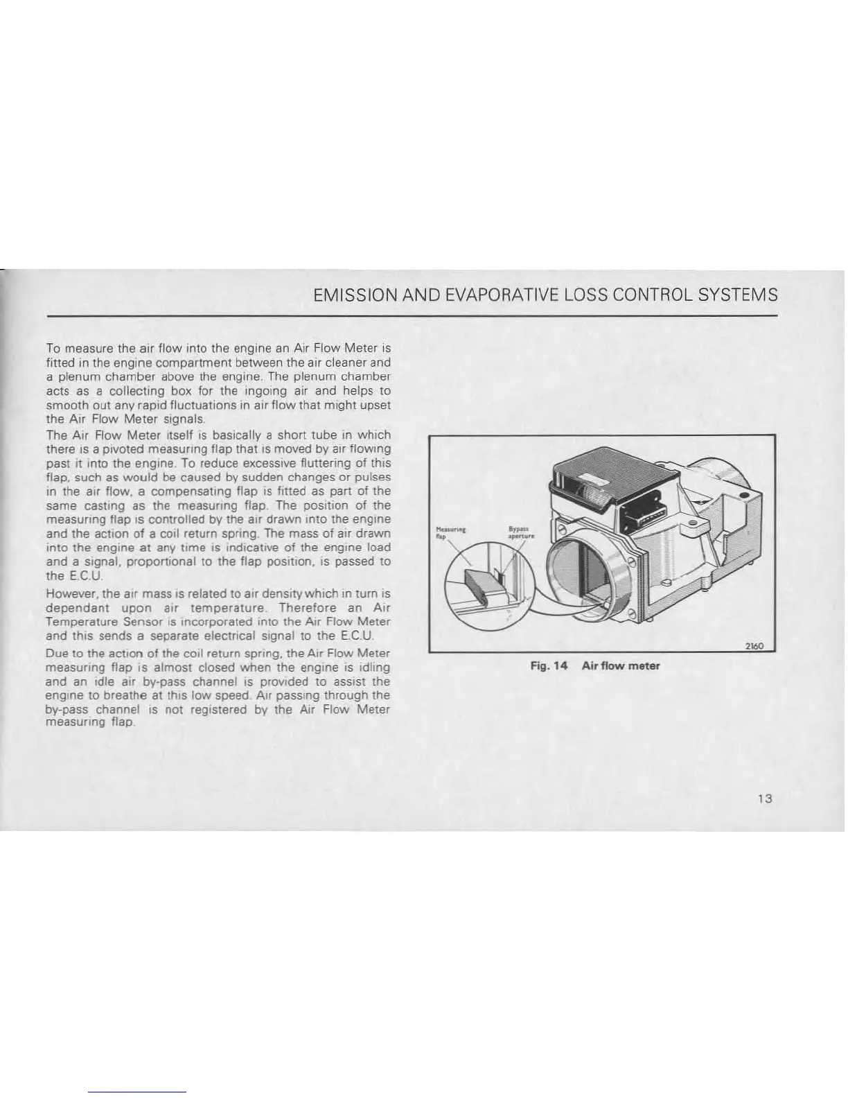
The AIr Flow
Meter
Iiself
IS
basically a short tube In
which
there is a pivoted measUring flap that
IS
moved by air
flowing
past It Into the engine To reduce excessive fluttering of this
flap, such as
would
be
caused
by
sudden changes or pulses
in the
air
flow. a compensating flap
IS
fllted as part of the
same
casting as the measuring
Ilap_
The position of the
measunng flap
IS
controlled
by
the
alf
drawn
into
the
engme
and the action
of
a coil return spring The mass
of
air
drawn
Into the engine
at
any time
IS
Indlcatrve
of
the
engine load
and a SIgnal. proportional
to
the flap position. is passed to
the
EC.U
However. the air mass
IS
related
to
air denSItY
which
In turn
IS
dependant
upon
aIr
temperature
Therefore
an
AIr
Temperature Sensor
IS
Incorporated
Into
the Air Flow
Meter
and this sends a separate electrical Signal
to
the
EC
U
Due to the action
of
the
COil
return spring. the
Air
Flow
Meter
measuring
flap
IS
almost
closed
when
the engine
IS
Idling
and an Idle aIr by-pass channel
IS
provIded to assIst
the
engine to breathe at this
low
speed
Air
passing
through
the
by-pass channel
IS
not
registered by the Air Flow
Meter
measuring flap
"."
Fig.14
Air
flow
m.t
....
13