16
Safety instructions
– Before using the Mover®XT4 outdoors for the first time,
practice with it to familiarise yourself with the functions of
the remote control and the Mover®XT4.
– Before each use of the Mover®XT4, check tyres and drive
rollers, removing any sharp stones and similar objects.
– The side slide switch on the remote control (ON / OFF)
also serves as an “Emergency Stop switch”. Switch the
side slide switch to “OFF” immediately in the event of any
abnormalities, e. g. uncontrolled behaviour of the manoeu-
vring system.
– No person must be present in the caravan during operation.
– There must be no persons (particularly children) inside
the turning and movement range (manoeuvring range) of
the mobile home.
– When engaging and disengaging and while operating the
Mover®XT4, care must be taken to ensure that no hair,
parts of the body, clothing or other parts on the body can
become caught in moving and / or rotating parts (such as
drive rollers).
– During manoeuvring, the distance between the radio
remote control and the middle of the caravan must not
exceed 10 m.
– In the event of a malfunction, apply the parking brake.
– In order to avoid tilting the caravan, when manoeuvring
on slopes the drawbar should be pointed downwards
(downhill).
– After manoeuvring, always apply the parking brake first,
disengage the drive rollers from the tyres and block the
wheels (especially on sloping surfaces!). The Mover®XT4
is not suitable for use as a parking brake for a parked
caravan.
– Always protect the radio remote control from unauthorised
access (paying particular attention to children).
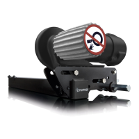
– Never tow the caravan with the drive rollers engaged, as
this may cause damage to the tyres, the towing vehicle and
the drive assemblies.
– All wheels and tyres on the caravan must be of the same
size and type.
– In order to ensure that the Mover®XT4 operates correctly,
the gap between the tyres and the disengaged drive rollers
must be 20 mm. All tyres must be inflated to the same press-
ure in accordance with manufacturer's instructions and
checked regularly. Tyre wear or the fitting of new tyres may
make it necessary to readjust the gap between the drive
rollers and the tyres (see “Fitting the drive elements”).
– When using a jack, the Mover®XT4 must not be used as a
jacking point, as this may damage the drive assembly.
– Sensitive objects such as cameras, DVD players etc. must
not be kept in the stowage box near the control unit or the
motor cables, as the powerful electromagnetic fields may
damage them.
– The empty weight of the vehicle is increased by the weight
of the Mover®XT4, thus reducing the vehicle's payload.
– Remove the plug / adapter from the safety socket after
manoeuvring, otherwise the battery will be discharged.
Quiescent current with plug / adapter inserted < 80 mA.
Quiescent current with plug / adapter unplugged < 150 µA.
Table of Contents
Symbols used ...................................................................... 16
Safety instructions .......................................................... 16
General instructions ........................................................ 17
Batteries ............................................................................ 17
Function description ...................................................... 17
Operating instructions
Remote control ................................................................. 18
Switching on the remote control ........................................ 18
Remote control LED blink code and audio signal ............... 18
Remote control battery change ......................................... 19
Disposal ............................................................................... 19
Manoeuvring the caravan ............................................... 19
Coupling to a towing vehicle ......................................... 19
Maintenance ..................................................................... 19
Checks ................................................................................. 20
Emergency disengagement ................................................ 20
Troubleshooting ............................................................... 20
Tuning the electronic control unit to the radio remote
control ................................................................................. 20
Technical data ................................................................... 21
EU Declaration of Conformity ....................................... 21
Manufacturer’s Warranty
(European Union) .............................................................. 22
Installation instructions
Intended use ........................................................................ 23
Approval .............................................................................. 23
Tools and facilities required ................................................ 23
Minimum installation dimensions ...................................... 23
Measuring the frame height ............................................... 23
Determining the installation type ........................................ 23
Special accessory installation ............................................. 24
Selecting a location ............................................................ 24
Mud guards ....................................................................... 24
Fitting the drive elements .............................................. 25
Electrical wiring and control unit ................................. 26
Connecting the battery ....................................................... 27
Connecting the safety socket ....................................... 28
Function check ................................................................. 28
Warnings ............................................................................. 28
Symbols used
The device must only be installed and repaired by an
expert.
Symbol indicates a possible hazard.
Note containing information and tips.
 Loading...