~ 19 ~
Any excess motor cable should then be coiled up (secure with cable ties as necessary) in a
convenient position inside the caravan/trailer When coiling the motor cables please ensure that
the coils are kept as far away from the electronics box and aerial as possible. It is
recommended that motor cables should NOT be cut to ensure that: -
1) They are of equal length
2) Should the Powrtouch Freedom be removed and refitted to a new or different
caravan then the cables can easily be reused.
Please ensure the battery is in good condition (See Section 5 Paragraph 5.4), a fully charged
leisure battery MUST be used and can be either a lead acid or gel type (Please note that car
batteries are not suitable to operate Powrtouch Movers.) A 110-Ampere hour battery is
recommended for optimum operation of the Powrtouch Freedom. Smaller batteries may be
utilised, but mover performance may be reduced. The aerial (thin black cable) should be let
through the caravan/trailer floor directly next to the ECB (drill a small 3mm hole as required)
and then run in a straight line away from the ECB and all motor cables. The aerial should be
clipped in place with the last 25mm (1 ins.) of the cable left dangling down. Under no
circumstances should the length of the aerial be changed either by cutting or extending by
splicing into it.
3.8 CONNECTING TO THE CARAVAN BATTERY
Please be aware of the need for access to the isolation switch when parking your
caravan/trailer. The switch should also be fitted to be in an accessible position whilst
the unit is in operation.
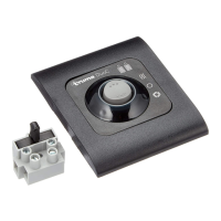
The Powrtouch is supplied with an inline switch which allows the isolation of the electrical
control box from the Battery. The suggested location for the fitting of this switch is in the sealed
side compartment within the battery box (see NOTE below), usually beneath the 240volt
mains connector. The reason for this location is to ensure that the Powrtouch isolation key will
obstruct the use of the 240-volt AC mains connector; under no circumstances should the
Powrtouch be operated while the caravan is connected to the 240volt AC supply. Drill a 25mm
hole with the hole-saw and the two 5mm clearance holes for the fixing nuts and bolts, when the
holes are drilled install the switch and tighten up the nuts and bolts.
The electronics control box, isolation switch and the in-line fuse MUST NOT be located
in the battery box or any compartments containing gas bottles. This is due to risk of
explosion caused by leaking gas and a spark generated by the electronics, isolation
switch or fuse.
The 16mm
2
battery cables are provided (Fig 6A3) correctly terminated for their application and
the length of these cables must not be altered in any way. The 1500mm Blue or Black
(negative) battery cable is connected directly from the negative terminal of the caravan battery
to the negative terminal of the ECB. NB. Starting from the non-terminated (bare end) 950mm
of this cable is double insulated, this part of the cable must be connected to the battery. The
1000mm Grey or Red (positive) battery cable is all double insulated. This cable is used to
connect the positive terminal of the battery (bare end) to one terminal of the inline fuse
positioned in the caravan. This fuse is provided to protect the ECB from overload or misuse.
The battery cables have to pass through 16mm dia. drilled holes in the battery box to gain
access to the caravan. These cables should be protected from chafing and the battery box
sealed from leaking gas by the use of self-adhesive seals (supplied). These seals MUST be
fitted. The 250mm Grey or Red (positive) battery cable connects the free terminal of the inline
fuse to a terminal of the isolation switch. The 750mm Grey or Red (positive) cable then
connects the second terminal of the isolation switch to the positive connection on the ECB.
Once connected these cables will then need to be securely fitted using the ‘P’ clips provided.