Intended use
This unit has been designed for installation in motor vehicles
with natural gas engines. Installation in boats is not permitted.
Other applications are possible subject to prior consultation
with Truma.
Always observe the operating instructions and the “Im-
portant operating notes” prior to starting! The vehicle
owner is responsible for correct operation of the appliance.
The installer or vehicle owner must affix the yellow warning
information sticker that is provided with the unit to the vehicle
in a location that is clearly visible to all users. Missing stickers
can be requested from Truma.
Control panel with slide switch
Fig. 5
a = Slide switch
Heating – Off – Ventilation
b = Slide switch for
Full power (large flame symbol)
Partial power (small flame symbol)
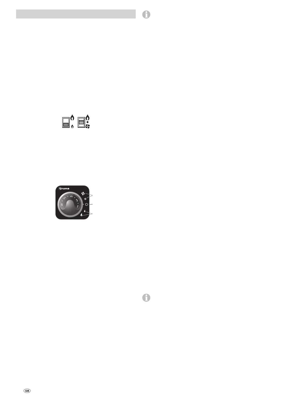
Control panel with rotary switch
Tr umatic E
d
c
e
Fig. 6
c = Rotary switch “Heating”
Full power (large flame symbol)
Partial power (small flame symbol)
d = Rotary switch “Off”
e = Rotary switch “Ventilation”
Full power (large symbol)
Partial power (small symbol)
Starting up the heating
– Remove the cowl cover.
– Open gas extraction valve.
– Open quick-acting valve in gas supply line.
– Set the desired room temperature at the control knob.
– Switching on the heater:
Control panel with slide switch
Set switch (a) to heating and switch (b) to the desired output.
Control panel with rotary switch
Set the rotary switch to the desired output (c).
At low outside temperatures, allow the heater to reach full
power.
The Trumatic E heater has been checked and approved
for operation while the vehicle is being driven. The
fan-assisted burner provides problem-free functionality, even
in the case of extreme wind conditions. National restrictions
for the operation of gas equipment while driving may need to
be taken into consideration.
Starting up the ventilation
Control panel with slide switch
Set switch (a) to ventilation and switch (b) to the desired output.
Control panel with rotary switch
Set rotary switch to the desired output (e).
Switching off
Set slide switch (a) or rotary switch (d) to the middle. If the
heater is turned off after heating, the fan may still run to util-
ise the residual heat.
If the device is not used for a long period, put on cowl cover
and close quick-acting valve in the gas supply line.
Green LED “On”
(beneath control knob)
When the device is on (heating or ventilation), the green LED
must light up (the fan is on). If the LED does not light up,
check the (main) switch if necessary. Please observe the re-
spective vehicle manufacturer’s instructions.
During heating, while the flame is burning, the green LED will
illuminate with double intensity. This can also be used to de-
termine the current switching point of the room temperature.
Fuses
The device and control panel fuses are on the electronic con-
trol unit on the device.
Device fuse (F1):
3.15 AT (slow-acting) – (EN 60127-2-3)
Control panel fuse (F3):
1.6 AT (slow-acting)
The fine fuse must always be replaced with a fuse of the same
type.
Red LED “Failure”
The red LED will illuminate if there is a failure. The causes of
this include, for example, lack of gas, lack of combustion air,
excessive dirt on the fan wheel, fuse fault etc. The failure can
be cleared by switching the system off and on again.
Opening a window to which a window switch is at-
tached and closing it again is the equivalent of switching
the equipment off and on again at the control panel (e.g. a
fault reset)!
A flashing light indicates that the operating voltage is too
low or too high for the heater (charge the battery if required).
In Germany, the Truma Service Centre must always be notified
in the event of faults; in other countries the respective service
partners are available (see www.truma.com).
Disposal
The device must be disposed of in accordance with the ad-
ministrative regulations of the respective country in which it is
used. National regulations and laws (in Germany, for example,
the End-of-life Vehicle Regulation) must be observed.
16
Operating instructions