Underfloor installation with wall cowl kit
See installation option picture 2 (page 2).
Fit wall cowl to a surface on an exterior wall (side skirt) that is
as flat as possible (see “Interior installation with wall cowl kit”).
If the wall cowl is installed with brackets or similar,
under the floor, the vehicle floor must be airtight and
the exhaust duct must always be routed at least as far as the
side wall (see “Selecting a location”).
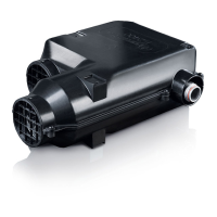
Mounting the heater
Screw the 3 fastening bows (1, 2 + 3) to the heater. Secure heater
to vehicle floor using lugs 1 + 2. Fix the fastening bow (4 – ac-
cessory part no. 39050-74000) and the lug (3) with screws (5).
Place spring washers beneath all screw heads and nuts.
Fig. 16
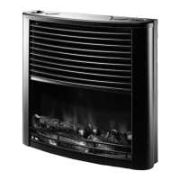
Warm air distribution and circulating
air return for interior installation
Warm air distribution
Heating air intake openings must be arranged so that exhaust
gas from the vehicle engine and the heater cannot be drawn in.
Structural measures must be taken in order to ensure that the
heating air that is led into the interior of the vehicle cannot be
contaminated (e.g. by oil vapours). This is done, for example, in
air heaters using circulating air operation both in interior instal-
lations and exterior installations (for air heaters using fresh air
operation, the fresh air must not be drawn in from the engine
compartment or the vicinity of the exhaust pipe or the exhaust
gas outlet of the heater).
The warm air (W) is blown out of the heater either directly or
through a warm air duct VR 80 (Ø 80 mm).
Remove the grid on the warm air outlet of the heater. Con-
nect VR 80 duct (Ø 80 mm). After installing a piece for the
duct branch, the VR 72 (Ø 72 mm), ÜR (Ø 65 mm) or ZR 18
(Ø49mm) duct can be routed further.
To prevent overheating, at least one air duct must be not
able to be closed (swivel air outlet SCW 2). Secure all duct
connections with self-tapping screws. Fix ducts with clamps.
The warm air system is designed individually for each vehicle
type using the modular design principle. A wide range of ac-
cessories is available for this purpose (see brochure). Diagrams
with optimum installation suggestions for warm air systems
can be requested free of charge from the Truma Service Centre.
Circulating air return
The circulating air (U) is drawn in by the heater again either
directly or via a VR 80 duct section (Ø 80 mm).
1. Direct intake: If the heater is installed in a storage box or the
like, drill 2 holes Ø 75 mm or make an opening of an appro-
priate size for the circulating air return.
Fig. 17
Do not obstruct the air routes to the heater!
2. Circulating air outside the storage space can be drawn
in through a VR 80 (1) Ø 80 mm (max. 1 m length) and
led back to the heater. The storage area can then be fully
utilised.
Remove protection grille from the connection (3). Place duct
section (1) into the grille connector and secure with the exist-
ing screws. Attach swivel air outlet SCW 2 to the end of the
duct (4).
min 0.5m
max 1m
3
1
4
W
U
Fig. 18
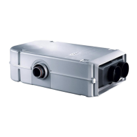
Warm air infeed and circulating
air return for external installation
See installation option picture 2 (page 2).
The warm air supply and the circulating air return between
the heater and the vehicle must be provided using the flexible
LF18 air ducts (Ø 83 mm, length 60 cm). The air ducts can be
shortened as desired. A protection box above the entire heating
system protects them from damage and weather influences
and also acts as additional insulation.
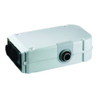
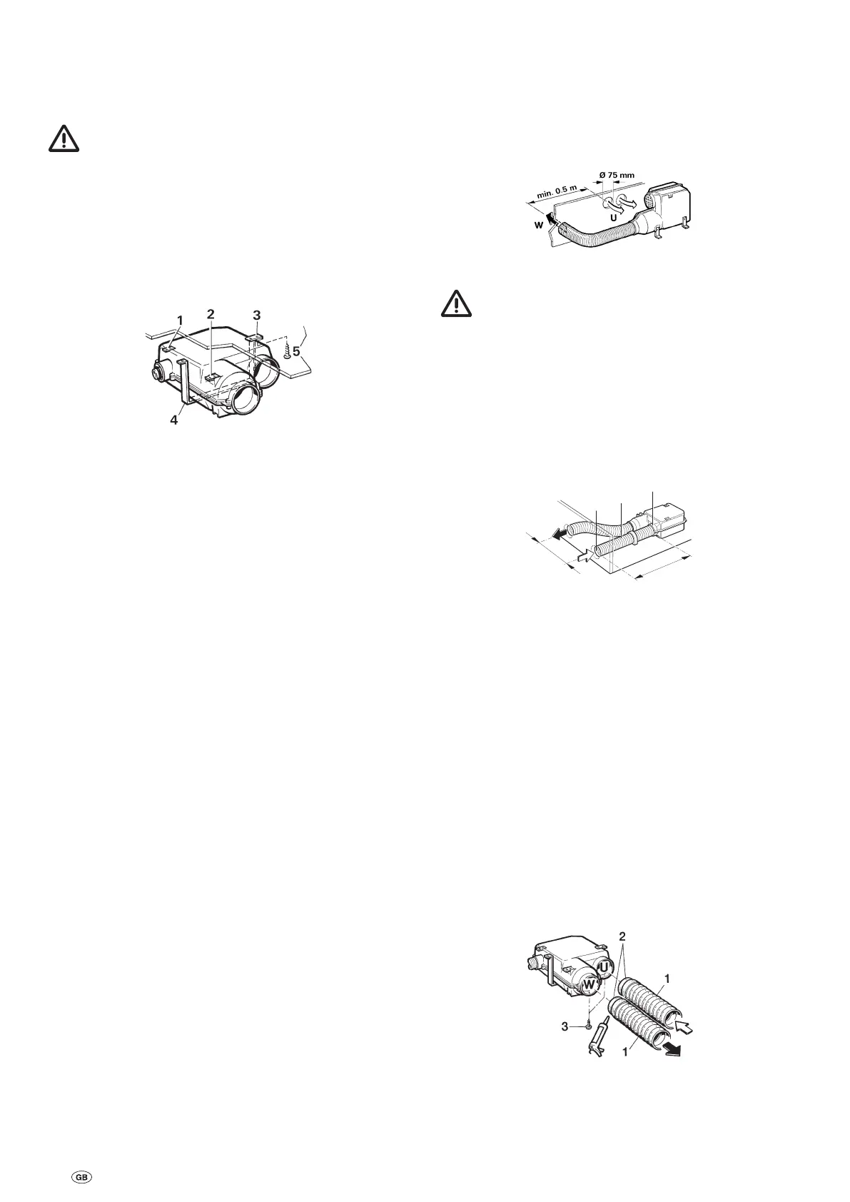
Connecting the ducts to the heater
Remove the two protection grilles from the heater. Coat both
duct sections LF 18 (1) with plastic body sealant at the stiffened
ends (2) and slide into the openings of the heater (W + U).
Secure with 2 self-tapping screws (3). The duct connection
must be fitted correctly, as otherwise spray water may find its
way into the heater!
Fig. 19
22