The unit must only be installed and repaired by an ex-
pert. Read the installation instructions carefully before com-
mencing the work, and then comply with them.
Disregarding installation instructions or erroneous
installation can put people in danger and cause
damage to property.
Intended use
This device was designed for installing in vehicles (motor
homes, cars and commercial vehicles). Installation in boats is
not permitted. Other applications are possible subject to prior
consultation with Truma.
Installation inside buses (vehicle classes M2 and M3) is not
permitted.
Vehicles EX/II and EX/III
Combustion heaters for gaseous fuel are not permitted.
Approval
The heater is approved for installation in motor vehicles for
transporting passengers (motor caravans in vehicle class M1)
with no more than 8 seats excluding the driver’s seat, for
trailers (caravans in vehicle class O) and for commercial ve-
hicles (vehicle class N).
The year when the equipment was first taken into oper-
ation must be indicated with a cross on the type plate.
Regulations
Guarantee claims, warranty claims and acceptance of liability
will be ruled out in the event of the following:
– Modifications to the device (including accessories),
– Modifications to the exhaust duct and the cowl,
– Use of replacement and accessory parts other than original
Truma parts,
– Failure to follow the installation and operating instructions.
The device’s operating permit, and consequently also the ve-
hicle’s operating permit in some countries, are also rendered
void.
The technical and administrative regulations of the country in
which the equipment is being used must be followed when
the equipment is being installed in vehicles. The national
rules and regulations (e.g. DVGW Worksheet G 609 Draft and
VdTÜV leaflet 757 in Germany) must be observed.
The relevant employer’s liability insurance association acci-
dent prevention regulations must be observed in Germany for
vehicles used for commercial purposes (BGV D 34).
In other countries, the relevant regulations must be observed.
More information about the regulations in the relevant des-
tination countries can be requested from our foreign represen-
tatives (www.truma.com).
Installation instructions for commercial vehicles
When installing the heater unit in special vehicles (e.g. vehicles
used for transporting dangerous goods), the applicable guide-
lines for such vehicles must be observed.
Installation instructions for driver cabs
For heaters with the exhaust duct beneath the vehicle floor,
the exhaust cowl opening must be brought to the side or rear
boundary of the driver’s cab or the vehicle. It must be ensured
that no exhaust gas can enter the interior of the vehicle (e.g.
from beneath the vehicle floor).
Type-specific assembly instructions and fitting kits are availa-
ble from Truma.
In Germany, the heater is only permitted in dangerous goods ve-
hicles under ADR when it is equipped with a Truma series unit.
Selecting a location
The device and its exhaust duct must always be installed so
that they are easy to access at all times for service work, and
also easy to remove and install.
In order to heat the vehicle evenly throughout, the heater
must be installed in a location in the vehicle that is as central
as possible, so that the air distribution ducts can be routed
with approximately equal lengths.
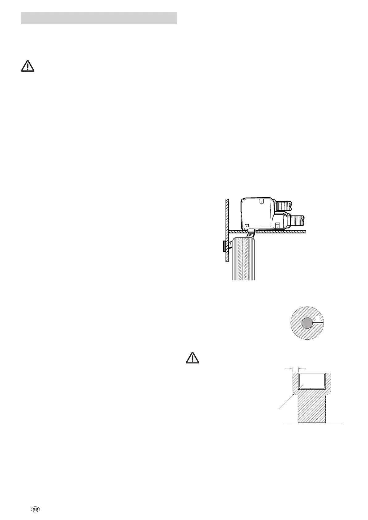
Cowls must be positioned so that no exhaust gas can enter
into the interior. The exhaust duct must always be routed at
least as far as the side wall.
Fig. 9
The wall cowl must be at-
tached so that there is no
fuel tank filler neck or fuel
tank breather opening within
500 mm (R). There must also
be no living area ventilation
openings or window openings
within 300 mm (R).
R
Fig. 10
If the cowl is being
installed in the shaded
area underneath or next to a
window that will be opened,
an electric window switch
(part no. 34000-85800) must
be installed. The gas unit must
automatically switch itself off
using the Truma automatic
shut-off device if the window
is opened (accessory part no.
39050-00800).
Fig. 11
20
Installation instructions