Exhaust duct
Only Truma exhaust duct AA 24 (part no. 39420-00) and com-
bustion air intake duct ZR24 (part no. 39440-00) may be used
for the Trumatic E 2400 E heater for installation with a wall
cowl, because the unit has been tested and approved only
with these ducts.
A new O-ring must be fitted whenever the exhaust duct
has been removed!
Permissible duct lengths
1. Interior installation with wall cowl
(see installation options 1, page 2):
– Duct lengths of up to 70 cm can be laid with any
amount of upslope or with a downslope of max. 30 cm.
– Duct lengths of 70 cm to max. 150 cm must be placed
with an upslope with an angle of incline of at least 45°.
2. Underfloor installation with wall cowl
(see installation option 2, page 2):
Cowl double duct length of up to 70 cm
Can be laid with any amount of upslope or with a
downslope of max. 30 cm.
Interior installation with wall cowl kit
See installation options picture 1 (page 2).
Installing the wall cowl
Fit the wall cowl to a surface that is as flat as possible so that
air can flow around at all sides. Drill opening (8) with a diam-
eter of 70 mm (duct hole must be lined with wood in cavities).
Seal with provided rubber seal (10). Use flexible body sealant
on textured surfaces – do not use silicon.
Fig. 12
In the case of thicker walls, first connect the exhaust double
duct to the cowl from the outside.
Slide rubber seal (10) and clamp (4) onto inner part of cowl (11).
1
Fig. 13
Compress beginning of exhaust duct (1) so that the coils are
tightly compacted, slide it over the O-ring (2a) on the con-
nection (2) as far as the collar (3) (cowl bend facing upwards)
and tighten clamp (4) so that the flanged rim of the clamp is
gripping the collar.
Coat the toothed connection (9) with plastic body sealant – not
silicon – and push the combustion air intake duct (5) over it.
Secure the cowl inner part (11) with 3 screws (12) (pay atten-
tion to the installation position. The Truma logo must be at
the bottom). Fit outer part of cowl (13) and screw on with 2
screws (14).
A new O-ring must be fitted whenever the exhaust duct
has been removed!
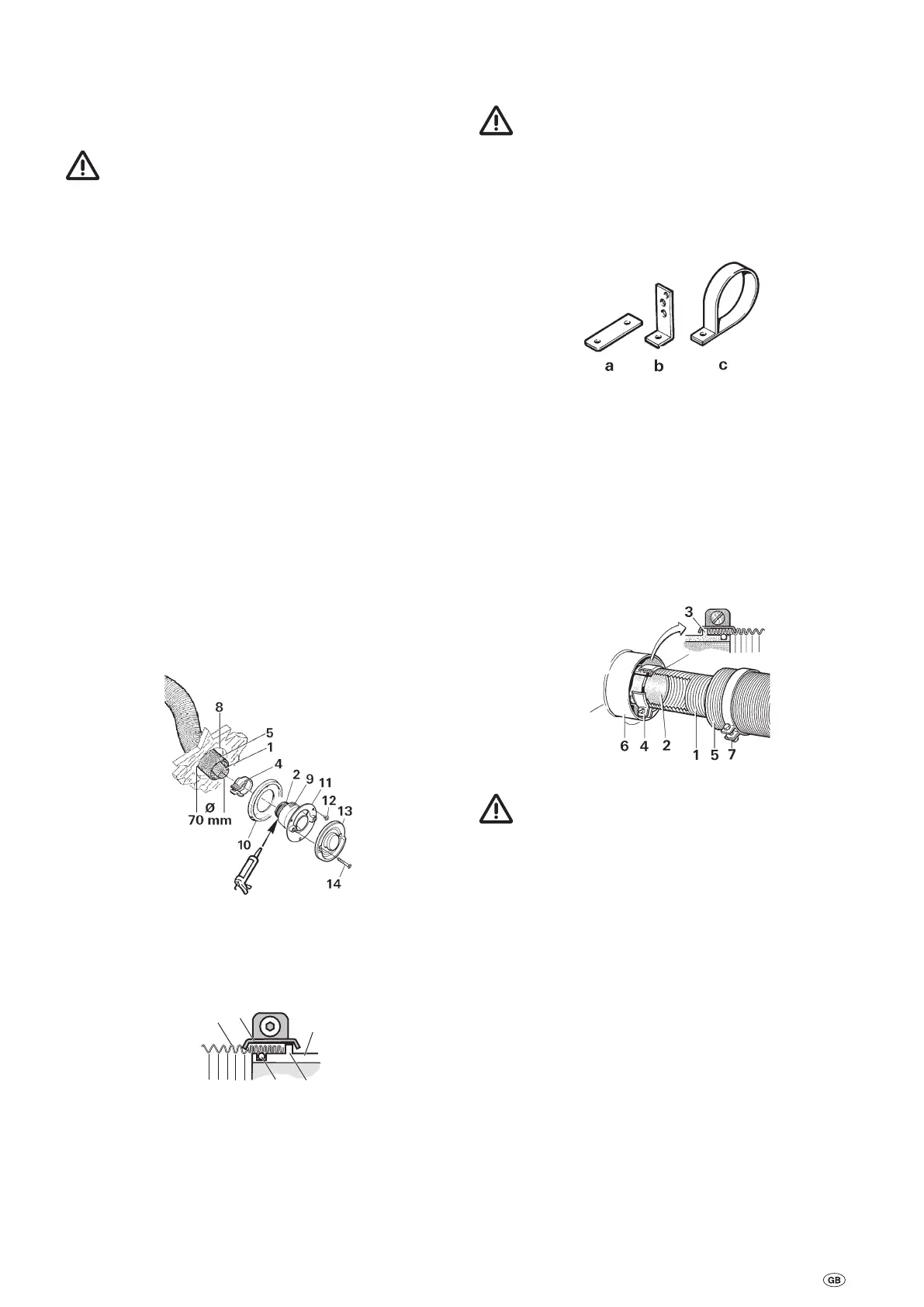
Mounting the heater
Depending on the installation position, securely screw the
heater into place with the fastening bow (a) or fastening
brackets (b).
Fig. 14
Attach the exhaust double duct to the wall with pipe clip ZR24 (c)
if necessary (parts contained in the accessory kit).
Double duct connection to the heater
Compress exhaust duct (1) at its beginning so that the coils
are tightly compacted. Slide clamp (4) over exhaust duct (1).
Slide exhaust duct over the O-ring on the connection (2) as far
as the collar (3). Secure with clamp (4) so that the flanged rim
of the clamp is gripping the collar. Slide combustion air intake
duct (5) onto connection (6) and secure with clamp (7).
Fig. 15
A new O-ring must be fitted whenever the exhaust duct
has been removed!
21