THE COOK DOOR
2.
O
pen and close the Cook D
oor several times to
ensur
e the Door closes smoothly and the Door
Actuator (Item 70) clears the slot in the Flange.
Reference Figure 26.
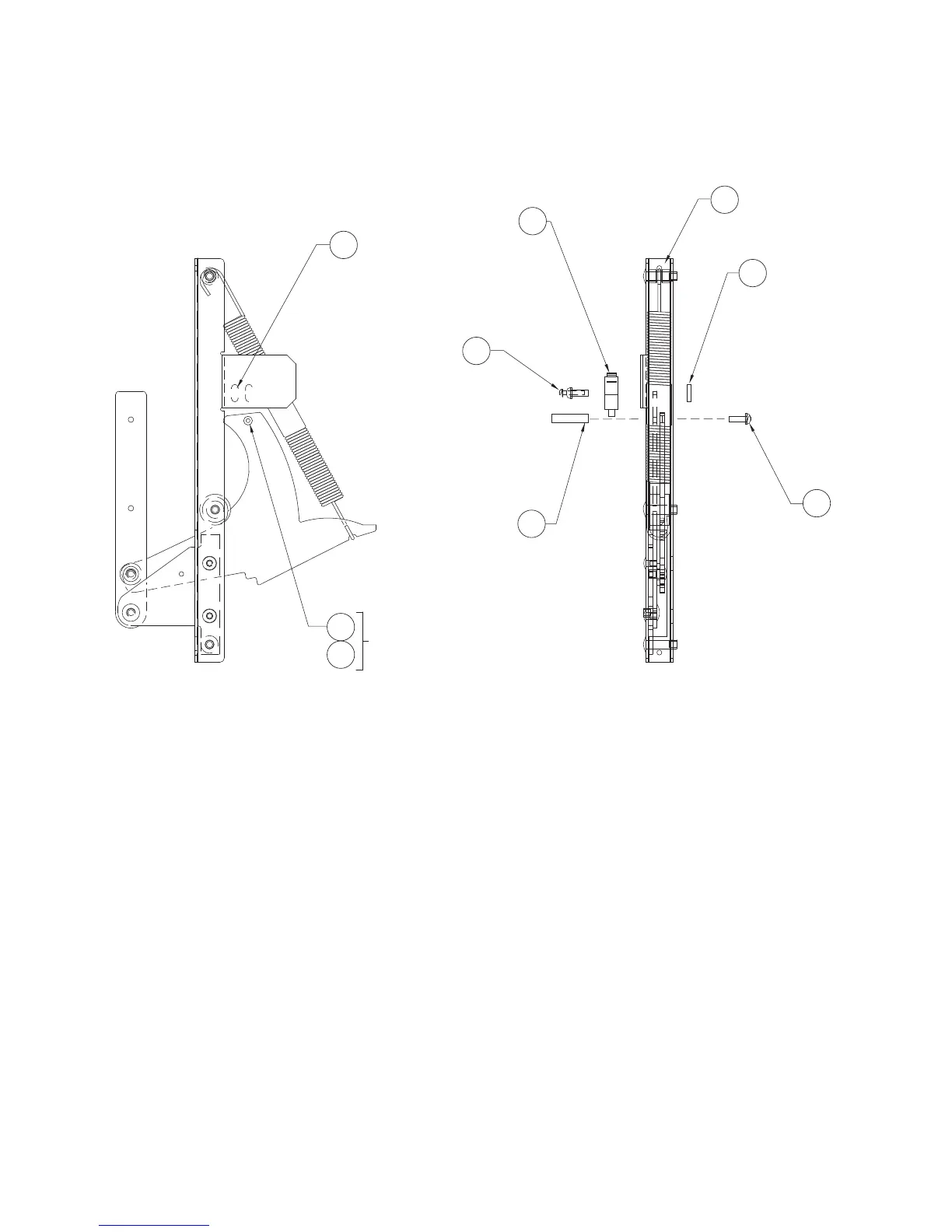
3. To adjust the Monitor Safety Switch (Figure 28),
loosen the #8-32 screw and the two (2) #4-40
scr
e
ws
(I
tems 74 and 75) securing the switch.
4.
Rotate the Monitor Safety Switch (Item 71)
until the gap between the Switch Paddle and
the Switch Body is 0.02 inch.
5.
O
pen and close the Cook D
oor several times to
make cer
tain the adjustment is correct.
6. Tighten all screws when adjustment is complete.
MONITOR SAFETY SWITCH PARTS
Figure 28
70. 102804 Hinge, Right
71. 102012 Switch, Limit, Micro
72.
NGC-1126
P
late, D
oor switch
73. 101912 Standoff, #8-32F/Fx1 in S
74.
102921
Screw, #8-32 x 3/8”
75.
102902 Screw, 4-40 x 5/8”
: Monitor Switch Adjustment and Assembly
37
 Loading...