A
B
C
D
E
-2-
2
3
4
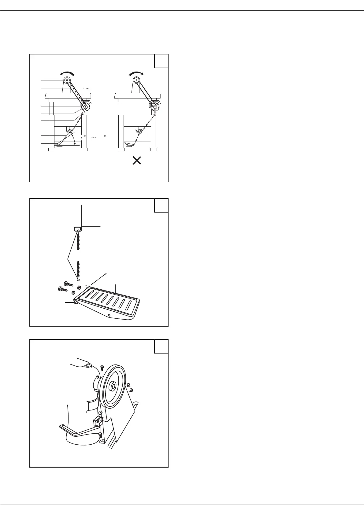
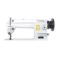
A. The optimum tilt angle of pedal with floor is
approx. 20 30 degree.
B. Adjust the clutch of motor so that clutch lever
(c) and draw bar (B) run in line, the machine would
have stable motion and long using.
C. The machine balance wheel should rotate
counterclockwise for normal sewing when view
form opposite side of the balance wheel the motor
rotates in the same direction. The rotation can be
reversed by reversing (turn over 180 degree) the
plug of the motor.
D. Adjust the tension of V-belt (F) by moving the
motor vertically. The proper tension of V-belt is a
slack of 10 12mm when the belt is depressed by
finger.
.
.
.
.
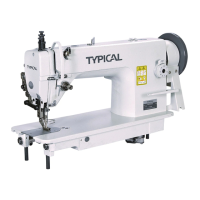
A. The optimum tilt angle of pedal with floor is
approx. 20 30 degree.
B. Adjust the clutch of motor so that clutch lever
(c) and draw bar (B) run in line, the machine would
have stable motion and long using.
C. The machine balance wheel should rotate
counterclockwise for normal sewing when view
form opposite side of the balance wheel the motor
rotates in the same direction. The rotation can be
reversed by reversing (turn over 180 degree) the
plug of the motor.
D. Adjust the tension of V-belt (F) by moving the
motor vertically. The proper tension of V-belt is a
slack of 10 12mm when the belt is depressed by
finger. .
.
.
.
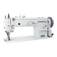
First the hook A should be connected to the chain
B and presser foot lift lever C, then put the pedal
compl te D on the stand. Move the control pedal E
leftward or rightward until the chain becomes on one
line. Tighten the bolts and nuts. Finally, connect the
finger to the control pedal.
e
.
First the hook A should be connected to the chain
B and presser foot lift lever C, then put the pedal
compl te D on the stand. Move the control pedal E
leftward or rightward until the chain becomes on one
line. Tighten the bolts and nuts. Finally, connect the
finger to the control pedal. .
e
Please install the belt guard for safety.
5. Connecting the clutch motor lever to
the pedal (Fig. 2)
6. Connecting the presser foot lift
control pedal (Fig. 3) .
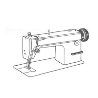
7. Installing the belt guard (Fig. 4)
10 12mm
20 30
A
B
C
D
E
F
G