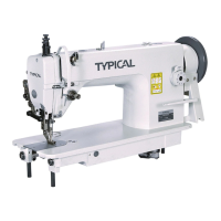
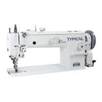
This document is an operation instruction and parts manual for the TYPICAL TW1-2B/TW1-2BL20 Single Needle Top and Bottom Feed Extra Heavy-duty Lockstitch Sewing Machine.
Function Description
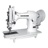
The TW1-2B/TW1-2BL20 is an extra heavy-duty lockstitch sewing machine designed for demanding applications. It features a single straight needle, a link thread take-up mechanism, and high-precision bevel gears for driving. A key characteristic is its large hook for catching thread, which contributes to its ability to handle extra heavy-duty and extra thick threads. The machine incorporates a special upper feed mechanism, enhancing its performance when sewing challenging materials.
It is widely used in industries and applications involving materials such as suitcases, leather, sofas, tents, and bamboo matting, where robust and reliable stitching is essential.
Important Technical Specifications
The manual provides a table outlining the key technical specifications for both the TW1-2B and TW1-2BL20 models:
- Max. Sewing Speed:
- TW1-2B: 1200 stitches per minute (s.p.m)
- TW1-2BL20: 900 stitches per minute (s.p.m)
- Max. Stitch Length: 13mm for both models.
- Presser Foot Lifting: 13mm by hand, over 13mm by knee for both models.
- Alternate Press Foot Lifting Range: 4mm to 6mm for both models.
- Timing of Walking Foot and Feed Dog: Max stroke is more than 13mm for both models.
- Rotating Hook: Extra large hook for both models.
- Needle: DDX1 24#~27# for both models.
- Lubrication: Lubricated by hand for both models.
- Clutch Motor: 0.5KW for both models.
Usage Features
The manual details various aspects of operating and preparing the machine for use, as well as adjustments for optimal performance.
Operation and Preparation:
- Cleaning: Before initial use, all parts coated with rust preventive grease must be cleaned with a clean cloth and gasoline to remove hardened grease and dust accumulated during storage and shipment.
- Examination: A thorough examination is required after cleaning to check for loose or deformed parts due to transportation. Turning the balance wheel helps identify any running obstructions, parts collision, uneven resistance, or abnormal noise, necessitating adjustments before operation.
- Clutch Motor Installation: The machine balance wheel belt groove (A) must be aligned with the motor pulley belt groove (B) by adjusting the motor's position.
- Clutch Motor Lever Connection to Pedal: The optimal tilt angle of the pedal with the floor is approximately 20-30 degrees. The clutch of the motor should be adjusted so that the clutch lever (C) and draw bar (B) are in line, ensuring stable motion and longevity. The machine balance wheel should rotate counterclockwise for normal sewing when viewed from the opposite side; the motor rotates in the same direction. The rotation can be reversed by turning the motor's plug 180 degrees. The tension of the V-belt (F) is adjusted by moving the motor vertically, with a proper slack of 10-12mm when depressed by a finger.
- Presser Foot Lift Control Pedal Connection: The hook (A) is connected to the chain (B) and presser foot lift lever (C). The pedal (D) is placed on the stand, and the control pedal (E) is moved left or right until the chain is aligned. Bolts and nuts are then tightened, and the finger is connected to the control pedal.
- Belt Guard Installation: The belt guard must be installed for safety.
- Bobbin Winder Installation: The pulley (B) of the bobbin winder is aligned with the outside of the belt (C). The stop latch thumb lever (A) should contact the belt when depressed. The bobbin winder pulley (B) should be parallel with the belt slit (E) of the table while the machine is running. The two wood screws are then tightened.
- Trail Run: For new machines or those unused for a long time, the rubber plug and face plate on the machine head should be removed, and the machine thoroughly oiled. The presser foot is lifted, and the machine is run at a low speed (200-400 s.p.m) for 30 minutes to ensure full lubrication. The speed is then gradually increased. After months of running, the speed can be increased to the proper sewing speed for optimal performance.
- Needle Installation: The balance wheel is turned to lift the needle bar to its highest position. The needle set screw (1) is loosened, and the needle shank is fully inserted up to the bottom of the needle clamp, with the long groove facing the operator's left side. The screw (1) is then tightened. Incorrect insertion (not fully inserted or wrong long groove direction) is highlighted as a common error.
- Coordination among Needle, Thread, and Material: Left-twisted needle thread and left- or right-twisted bobbin thread are recommended. The manual explains how to identify left-twisted thread by twisting it with the right hand in the direction of the arrow until it tightens. The needle model DDX1 24# to 27# should be chosen based on the material; using too thin a needle for heavy-duty materials can cause breakage and skipped stitches, while too heavy a needle can damage the fabric.
- Threading the Needle Thread: The needle bar must be in its highest position for correct threading, which involves a specific sequence through various retainers, tension discs, fingers, and guides.
- Winding Adjustment: Bobbin thread should be neat and tight. Tension is adjusted by turning the tension stud thumbnut (A) of the bobbin winder tension bracket. If the thread layer is not cylindrical, the tension bracket screw (B) is loosened, and the bracket is moved left or right until the thread is cylindrical. Nylon or polyester thread should be wound with light tension to prevent bobbin breakage or deformation. The bobbin should be filled to about 80% of its outside diameter, adjustable by the stop latch screw (E).
- Adjusting Forward and Reverse Stitch Length: Stitch length is adjusted by moving the adjusting spanner (A). Turning it clockwise shortens the stitch, while counter-clockwise lengthens it. After adjustment, the stitch length should be tested on paper. If the reverse stitch length is shorter than the forward stitch, screw (C) is turned counter-clockwise, and the nut is tightened. If it's longer, screw (C) is turned clockwise. Screw (D) can also be used for adjustment.
- Adjusting Pressure of Presser Foot: Pressure is adjusted based on the material. Loosen locknut (A). For heavy materials, turn the presser regulation thumbscrew clockwise (a) to increase pressure. For light materials, turn it counter-clockwise (b) to decrease pressure. Then tighten locknut (A). Proper pressure allows normal material feeding.
- Installing Bobbin and Adjusting Thread Tension: Thread tension is adjusted according to material and thread type, typically to achieve desired sewing stitches. This involves changing tension on both bobbin and needle threads. Bobbin thread tension is increased or decreased by turning the screw on the bobbin case with a small screwdriver. Needle thread tension is adjusted by changing the take-up spring tension and range, tension spring tension, and the position of the tension disc and thread finger.
- Adjusting Thread Take-up Spring: The normal sewing range is 5-8mm. For light duty materials (small stitch length), spring tension is weakened, and range widened. For heavy duty materials, tension is strengthened, and range shortened. Tension is increased by turning screw (A) clockwise, and decreased by turning it counter-clockwise. The sewing range is adjusted by loosening screw (A) and turning tension disc (B) clockwise to increase range, or counter-clockwise to decrease range. This is usually pre-adjusted and only needs readjustment for special materials or threads.
- Adjusting Tension of Needle Thread and Bobbin Thread: Normal stitches should appear as shown in Fig (a). Abnormal stitches (puckering or thread breakage) require tension adjustment. If needle thread is too strong or bobbin thread too weak, turn the needle thread tension regulating thumb nut counter-clockwise for less tension, or tighten the bobbin case tension regulating screw for more tension. If needle thread tension is too weak or bobbin thread too strong, turn the needle thread tension regulating thumb nut clockwise for more tension, or turn the bobbin case tension regulating screw counter-clockwise for less tension. Other abnormal stitches (d, e) can be adjusted using these methods.
- Timing between Needle and Rotating Hook:
- Adjusting Needle Bar Position: Turn the balance wheel to bring the needle bar (B) to its lowest position. Remove face plate (A). Vertically move needle bar (B) until the center of the needle eye (C) aligns with the inside surface (D) of the rotating hook. Tighten the screw.
- Adjusting Timing between Rotating Hook and Needle: This affects sewing quality. Standard timing: Turn balance wheel to bring needle bar to its lowest position, then lift it 3.8mm. The rotating hook head point (D) should align with the needle centerline (C). At this point, hook head point (D) should be 2-2.5mm higher than needle eye (E). When adjusting, ensure the clearance between the hook head point and needle side is 0-0.1mm.
- Installing and Uninstalling the Hook: Lift the needle bar to its highest position, remove needle plate, needle, and bobbin case. Loosen bobbin case holder bracket screw (C) and remove position bracket (A). Loosen set screw (B) to allow the rotating hook to turn freely. Turn the balance wheel to raise the feed dog support. Slowly remove the rotating hook while turning it away from the feed dog support. Installation is the reverse process. The projecting flange of position bracket (A) must engage the notch of the bobbin case holder, with a clearance of 1.1-1.3mm.
- Installing the Hook Stop Bracket: Before installing stop bracket (E), loosen screw (D). Adjust the clearance between the stop bracket and hook to 1.2-1.5mm. The elastic tension of stop spring head (C) should be 1-1.2mm to effectively limit the bobbin case. Ensure (C) does not touch (B). Tighten screw (D).
- Installing the Feed Dog:
- Standard Position: When feed amount is at maximum, the front end of feed dog (A) should be 1.5mm from the front of the needle plate slot.
- Adjusting Feed Dog Position: To adjust, move the feed to the front of the needle plate, loosen screw (A) (Fig 23b), and move feed dog support (B) in the direction indicated by the arrow. Tighten screw (A) after adjustment.
- Feed Timing Adjustment:
- Standard Position: Turn the balance wheel to lower feed dog (A) until it is horizontal with the needle plate surface (B). At this point, the needle tip (C) should also be horizontal with the needle plate and feed dog. Adjustment is made by adjusting the positions of the feed cam and feed dog lift cam.
- Installing Feed Dog Lift Cam: Open the backside cover. Turn the balance wheel counter-clockwise to lift the needle bar to its highest position. The first screw of the lift cam (counter-clockwise direction) should have a tilt angle of 45 degrees counter-clockwise. Tighten the screw.
- Installing Feed Cam: After installing the feed dog lift cam, install the feed cam. Using the feed dog lift cam as a reference, when the needle bar is at its highest position, screw (A) should have a tilt angle of 30 degrees counter-clockwise. Tighten screw (B).
- Upper Feed Adjustment: The center gauge (L) between the walking foot sliding block and its shaft can be adjusted based on the friction coefficients of materials and the sewing process. Increasing L enlarges the upper feed amount, while reducing L shortens it. For specific sewing requirements (e.g., upper layer needing more feed than lower layer), adjustments can be made within this theory.
- Adjusting Clearance between Presser Foot and Walking Foot: A clearance (C) of approximately 1.5mm should be maintained to prevent the walking foot from striking the presser foot. If the clearance is too small or too big, loosen the rear crank screw and turn the rock shaft, moving the walking foot near the needle bar. Note the fixed number of clearance (C) during adjustment.
Maintenance Features
The manual emphasizes the importance of regular cleaning for maintaining machine performance and longevity.
- Periodical Cleaning: The feed dog, rotating hook, and bobbin case should be cleaned according to machine usage conditions.
- Cleaning the Feed Dog: Remove the needle plate, clean dust and lint from the feed dog slit (A), then reinstall the needle plate.
- Cleaning the Rotating Hook: Clean all dust around the rotation hook (B) and clean the bobbin case with a soft cloth.
- Oiling the Thread Take-up Parts: The thread take-up parts use woolen thread oiling. After prolonged use, if their function is lost, they must be replaced. This involves opening the faceplate, removing the pressure screw, lock nut, and adjusting bar. Pin (A) is removed, and the old oil wick is drawn out. The oil wick in part (B) is also drawn out. New oil wicks are then installed, and the process is reversed for reassembly.