-8-
18
19
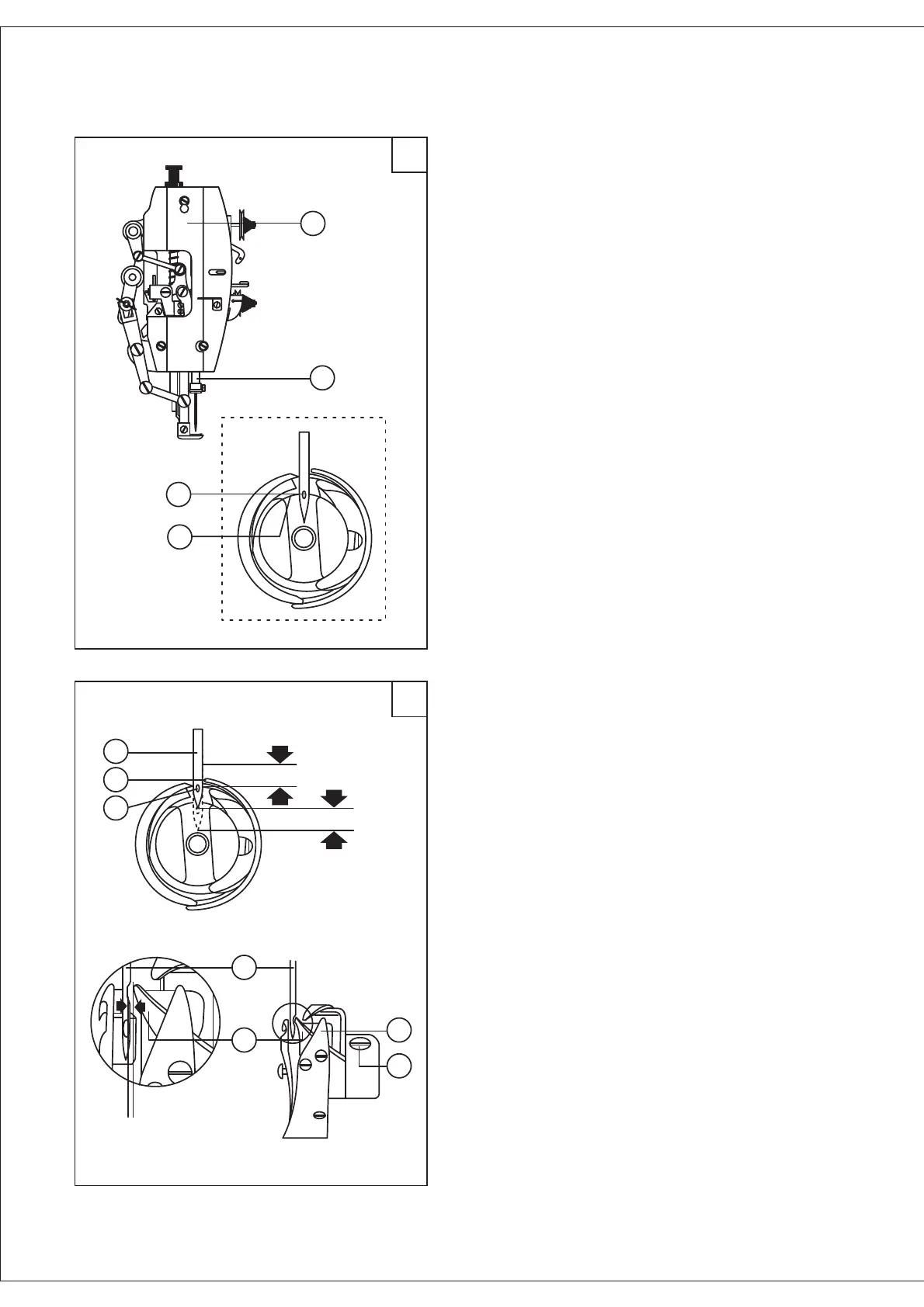
(1) Adjusting the position of needle bar.
Turn the balance wheel to make the needle bar (B)
to its lowest position. Remove the face plate (A), and
move the needle bar (B) vertically to locate the timing
position (the timing position of the needle bar is:
when the needle bar at its lowest position, the center
of needle eye (C) coincide with the inside surface (D)
of rotating hook). Tighten the screw.
.
.
.
.
.
(2) Adjusting timing between rotating hook and
needle.
The motive relation between rotating hook and
needle affects the sewing quality. Standard timing
relation is: Turn the balance wheel to locate the
needle bar to its lowest position and lift back 3.8mm
height. The rotating hook head point (D) should be
coincides with the needle centerline (C). At this time,
the hook head point (D) is 2 2.5mm higher than the
needle eye (E).
When adjusting the timing relation, also please
notice the clearance between the hook head point and
side of needle. The clearance should be 0 0.1mm.
(1) Adjusting the position of needle bar. .
Turn the balance wheel to make the needle bar (B)
to its lowest position. Remove the face plate (A), and
move the needle bar (B) vertically to locate the timing
position (the timing position of the needle bar is:
when the needle bar at its lowest position, the center
of needle eye (C) coincide with the inside surface (D)
of rotating hook). Tighten the screw. .
(2) Adjusting timing between rotating hook and
needle. .
The motive relation between rotating hook and
needle affects the sewing quality. Standard timing
relation is: Turn the balance wheel to locate the
needle bar to its lowest position and lift back 3.8mm
height. The rotating hook head point (D) should be
coincides with the needle centerline (C). At this time,
the hook head point (D) is 2 2.5mm higher than the
needle eye (E). .
When adjusting the timing relation, also please
notice the clearance between the hook head point and
side of needle. The clearance should be 0 0.1mm. .
21. Timing between the needle and the
rotating hook (Fig. 18,19)
C
D
E
2~2.5mm
3.8mm
0~0.10mm
D
C
A
B
A
B
C
D