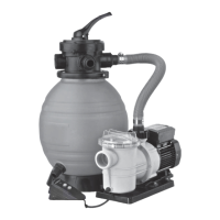
Pool Filter 400 / 500 / 600 - Pool Filter Sets 400-4m
3
/h / 400-6 m³/h / 500-9 m³/h / 600-13 m³/h
1
- HYDRA
LIC C
NNECTI
NS
1
T
r
t
re
e
c
nnecti
M
t
et
m
tic
nne
va
ve
i
avin
ef
reh
n
c
vere
t
rea
in
i
c
re
Te
on
urns
Thi
connect
on
be
xed
h
UM
-VALVE connect
o
pe
hi
y
separa
rom
h
p
pe
T
c
nnect
n
e
n
en
revious
ositione
n
r
w
nnect
n
T
r
t
er
ET
N
n
WA
T
t
ets
t
re
e
c
nnecti
ns
i
or
ettin
osition
in
t
re
”RETURN” - Out
et to
isc
ar
e tu
es
”PUMP” - Inlet
lter, corresponding to discharge o
the pump
”WASTE” - W
ster
t
e
4
T
h
nc
nnec
h
ther
n
f
h
c
nnecti
n
i
e
h
u
t
generate t
c
nstr
int in
h
c
nnecti
i
e
m
k
h
m
ltich
nnel
lve
wiv
r
n
i
ertic
l
xis
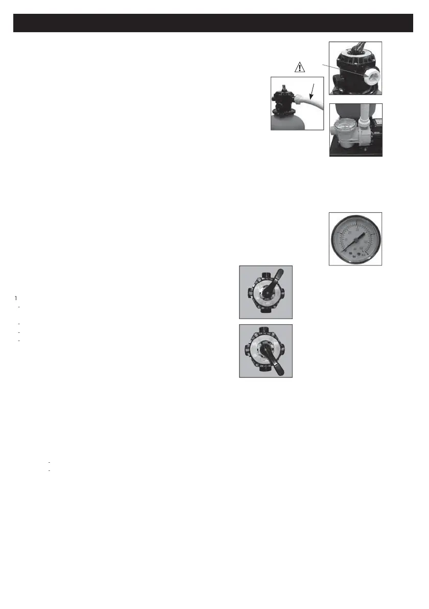
5
nally tig
ten t
e
w
o
ep
pe c
amp.T
e
a
ve
s
winter
epen
ent
t
an
an
sea
ing
assure
connec
t
e
u
uction
orizonta
y
t
ump
t
immer an
t
ETU
out
e
va
ve
t
isc
arg
u
e
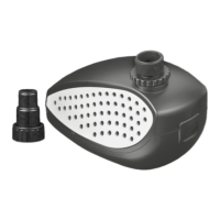
Accor
in
omo
e
o
swimming
oo
,t
o
it
er
groove
nozz
an
exibl
tu
e
it
iameter
ozz
es
o stic
an
t
i
e
o
5
in
iameter
I
o
exibl
tu
es
t
u
sea
ing
i
am
s.
o
nvisa
raina
e
i
e
not
rovi
e
t
e
A
T
ut
et
or
as
wa
er
t
ossi
e
a
s
env
sa
e
insta
ation
s
o
va
ve
t
s
immer an
anot
e
t
reversa
o
t
sw
mm
n
oo
ow,
r
e
ea
e
insu
ate t
ltratio
p
at
e poo
in particu
a
fo
t
ec
eanin
o
t
e
u
as
e
an
winterin
..
STMENT
F PRESS
RE GA
GE
ti
a
visa
e
egu
ar
oo
a
t
e
u
tate
t
u
u
in
icates
e
eve
aturation
f
lter
T
t
e lte
c
o
e
e
rea
e
e
u
.
T
u
u
i
rovi
e
wit
remova
e
ma
in
i
ossi
et
in
icate t
u
ratin
Be
on
r
f
v
u
,t
t
ashin
lter
- START
P
Th
r
eratio
c
nsist
in removin
l
h
st c
nt
ine
n
h
s
n
lac
h
v
lve in
WA
HIN
osition.
oactivatet
e
u
o
ew minute
unti
emu
ying in
icato
is
ean.
t
ma
e
u
a
wa
er circu
ate
norma
an
t
a
t
u
as
orrect
tarte
.
s
op t
e pump.
p
ace t
eva
v
nt
e
RIN
IN
ositio
ctiv
t
e
u
f
2
sec
n
s approximate
.
T
sto
h
um
.
T
ltr
ti
n
u
i
rea
f
ncti
n
4-
PERATI
N
RIFIC
UM
IMP
RTANT
NEVER ACTIVATE THE VALVE WHILE THE P
MP IS
PERATING
NEVER REM
VE PARTS IF THE FILTER IS PRESSURISED.
HECK THE
NCL
SING S
CTI
N N
ZZLE
1
FILTRATI
N
e
t
ev
ve
“FILTRATI
N”
t
r
h
u
W
te
will
e
ltere
through
h
s
n
TE
ote
n
recor
t
e
u
ea
in
ow
t
u
u
t
rs
me t
e
ys
em
s
operat
on.
T
i
ea
in
wi
y
u
future reference
u
P1”for
egu
a
peration.
RIN
IN
FILTER
I
t
e operating
u
excee
t
e
eference
u
“P1
t
an
.
ar
e san
us
e
inse
1
to
t
e
um
.
2)
h
v
lve t
“RINSE”
3)
t
rt
h
u
n
l
i
ntil
h
cl
iness st
t
sin
ic
t
r signal
th
h
le
nliness h
s
een
chieve
4
top t
e
u
.
5
e
t
eva
ve a
“FLUSH”
F
us
e
t
e
ines
n
isc
arges into t
w
ystem.
6
activat
e pump
urin
secon
s.
to
t
e
u
an
e
urn
o
FILTRATI
N
mo
e.
7)
t
r
the
u
he
operatin
u
m
st
r
wge
cl
se
t
Recommendations
or
ltration
1
It is essentia
to c
ec
t
at t
e suction openings are not o
structe
;
2) It is advisable to stop the
ltration during maintenance operations on the
ltration system;
3) Regularl
monitor the lter clogging level;