Step 2: Mounting the limit switches Assembling the frame 12
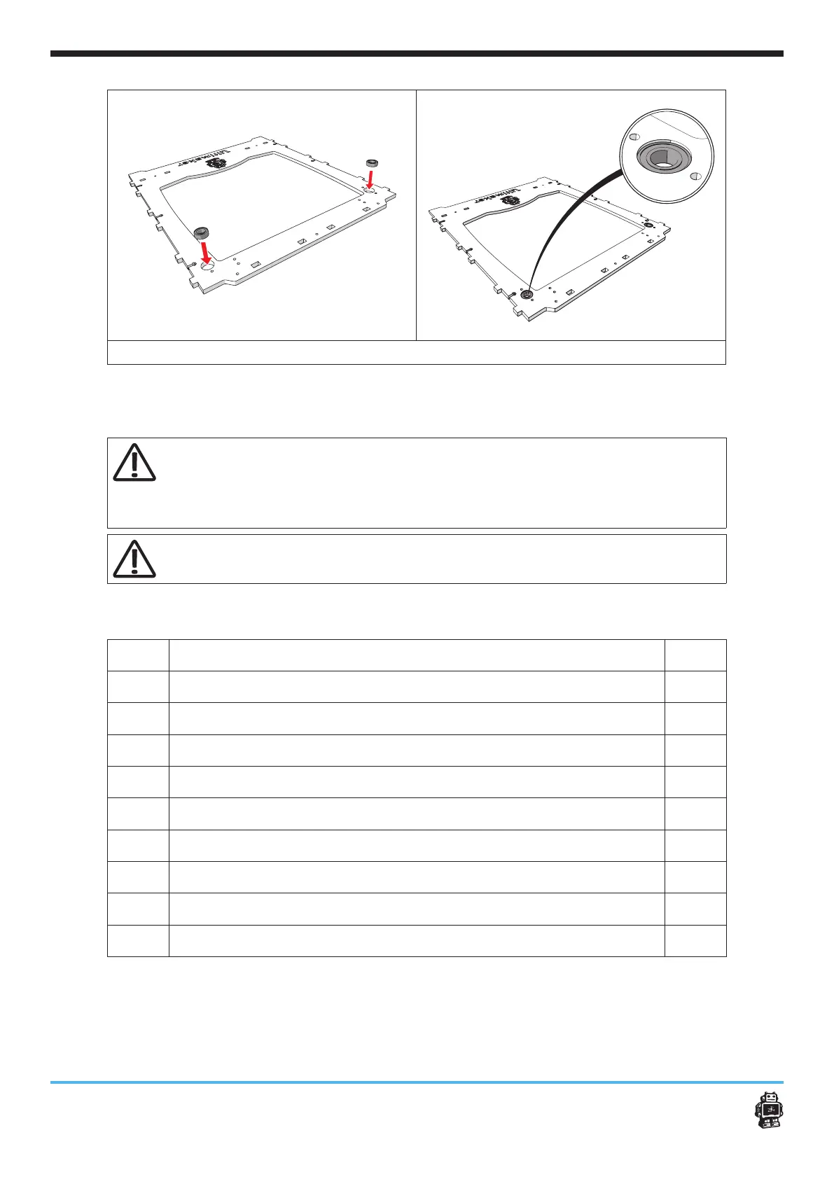
image 3: placing the ball bearings into the panel
6.1.2. Step 2: Mounting the limit switches
Warning! Do not strain the tapped thread on the inside of the switch
housing by putting a lot of force on the bolts. All limit switches are
pre-tapped, you can fasten them directly with M3 bolts, no nuts
required here!
Caution! Note that all wires of limit switches need to be twisted,
/!!Ƭ%)#!ąċ
The following parts are needed in this step.
Letter Description Qnty.
A
FRONT panel 1
B
LEFT panel 1
C
BACK panel 1
D
RED wired limit switch 1
E
BLUE wired limit switche 1
F
BLACK wired limit switch 1
G
bolts M3 x 12mm 4
H
bolts M3 x 16mm 2
I
washers 2