4-60 1000 Series / Guide to Installation, Troubleshooting, and Maintenance
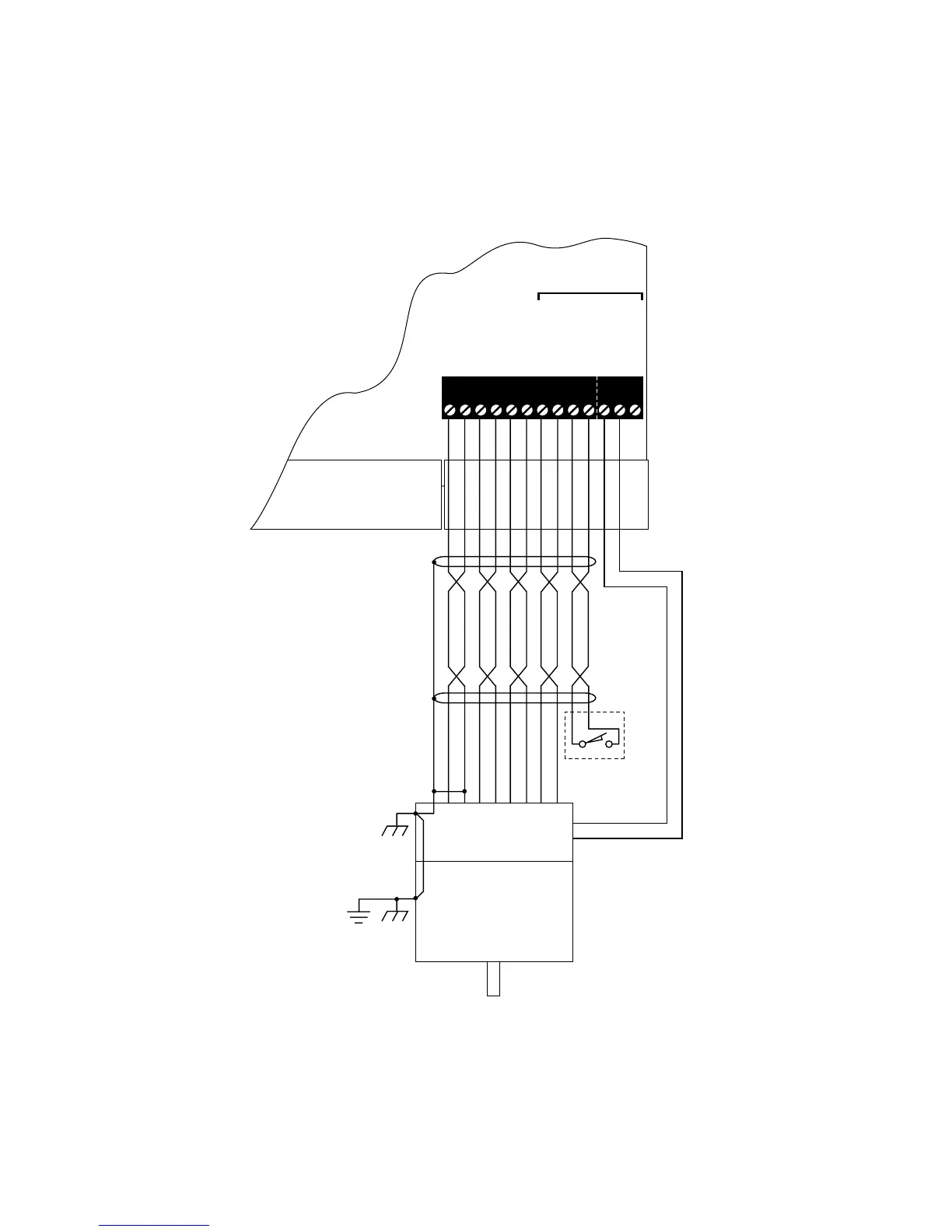
Figure 4-17—On-Board Encoder Interface Module Connections (100
MHz Controllers 323-397 and 323-547, 270 MHz Controller 324-260,
Compact 100 MHz Controller 323-060, and Compact 150 MHz
Controller 323-667)
1 2 3 4 5 6 7 8 9 10 11 12 1310 11 12 13 14 15 16 1718 19 20 21 22 23 24
1 2 3 4 5 6 7 8 9 10 11 12 13
CON19
CON23
(terminals 1-10 only)
CON15
Marker should
For use with
absolute/incremental
encoders only
occur once
per revolution
Encoder
Motor
PE
Motor case must
be earth grounded
Tie encoder case
to motor case
isolated Common
Tie shield to
Optional
and to encoder case
open this end
Leave shield
ISOLATED +5 V DC
ISOLATED COM
PGA +
PGA –
PGB +
PGB –
MARKER +
MARKER –
REFERENCE +
LOAD INPUT
LOAD OUTPUT
+15 V DC
REFERENCE –
Optional
 Loading...