Description
Overview of Connectors, Buttons and LEDs
Description
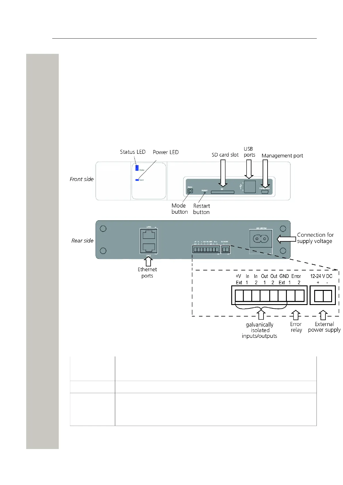
The Wireless Service Gateway WSG front side has different status indications and is used for
maintenance. The LEDs indicates the status of the module and the management port makes it
possible to have direct connection to the module. It also has an SD card slot and two USB ports
for external temporary devices.
The rear side is used for connecting supply voltage, communication to Ascom systems, external
systems, inputs/outputs etc.
Overview of Connectors, Buttons and LEDs
Figure 2: Connections, Buttons and LEDs
Front side
Status LED Indicates the module status, see LED Indications on page 11
Power LED Indicates the power status, see LED Indications on page 11
USB port 1
USB port 2
for upgrade of the Boot software on the field.
A31003-M2000-J109-01-7631, 30/06/2020
10 Wireless Service Gateway WSG, Installation Guide

 Loading...