Page 17
Radial 8 & 88 Operation Reference Manual 49379902 Rev. G
This Document Supports IM-UPS 5.0 and Higher
START Push Button
Use the START push button to initiate the production mode from the stop
mode. The START push button is illuminated when it is active and can be
used to start the machine. This button will not function when the machine is
in maintenance mode. The START push button is located on the control
panel on the first 20 station sequencer module.
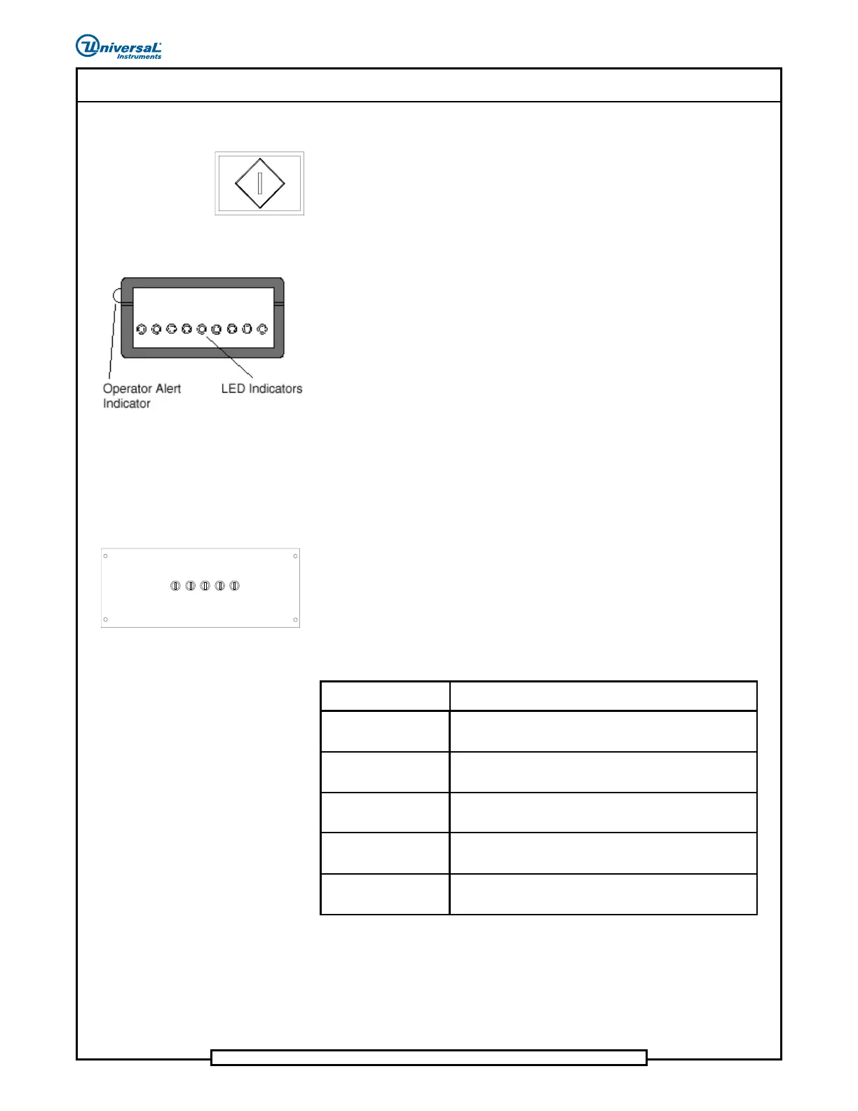
Sequencer LED Indicators
The sequencer LED indicator is mounted on top of each sequencer module.
The LED indicator illuminates (Low Part Condition) showing which
dispensing head is nearly out of components.
Each LED indicator represents a specified dispensing head location.
The operator alert indicator illuminates to show the operator which sequencer
module has a dispensing head that is starting to run out of components.
Sequencer Fuse Panel
The sequencer fuse panel contains the fuses that protect the 24 VAC wiring
to the dispense heads.
DISP HD
1-20
8A, 32V
SLOW BLOW
8A, 32V
SLOW BLOW
8A, 32V
SLOW BLOW
8A, 32V
SLOW BLOW
8A, 32V
SLOW BLOW
DISP HD
21-40
DISP HD
41-60
DISP HD
61-80
DISP HD
81-100
1FU
2FU 3FU 4FU 5FU
Function of Sequencer Fuse Panel Fuses
FUSE FUNCTION
1FU DISP HD 1-20
Fuse 1FU (8 amp, 32V slow blow) protects the switched
24VAC wiring to sequencer dispense heads 1 - 20.
2FU DISP HD 21-40
Fuse 2FU (8 amp, 32V slow blow) protects the switched
24VAC wiring to sequencer dispense heads 21 - 40.
3FU DISP HD 41-60
Fuse 3FU (8 amp, 32V slow blow) protects the switched
24VAC wiring to sequencer dispense heads 41 - 60.
4FU DISP HD 61-80
Fuse 4FU (8 amp, 32V slow blow) protects the switched
24VAC wiring to sequencer dispense heads 61 - 80.
5FU DISP HD 81-100
Fuse 5FU (8 amp, 32V slow blow) protects the switched
24VAC wiring to sequencer dispense heads 81 - 100.