monitoring & parameters vacon • 17
24-hour support +358 (0)201 212 575 • Email: vacon@vacon.com
5
NOTE! These parameters are shown, when P17.2 = 0.
Motor identifica-
tion
01 0631
0 = Not active
1 = Standstill identification
(need run command within
20 s to activate)
Rs voltage drop 0,00 100,00 % 0,00 662
Voltage drop over motor
windings as % of U
nmot
at
nominal current
Overvoltage
controller
02 1607
0 = Disabled
1 = Enabled, Standard
mode
2 = Enabled, Shock load
mode
Undervoltage
controller
01 1608
0 = Disable
1 = Enable
Sine filter 0 1 0 522
0 = not in use
1 = in use
Modulator type 0 65535 28928 648
Modulator configuration
word:
B1 = discontinuous modu-
lation (DPWMMIN)
B2 = Pulse dropping in
overmodulation
B6 = under modulation
B8 = instantaneous DC volt-
age compensation*
B11 = Low noise
B12 = Dead time compen-
sation*
B13 = Flux error compen-
sation*
*Enable by default
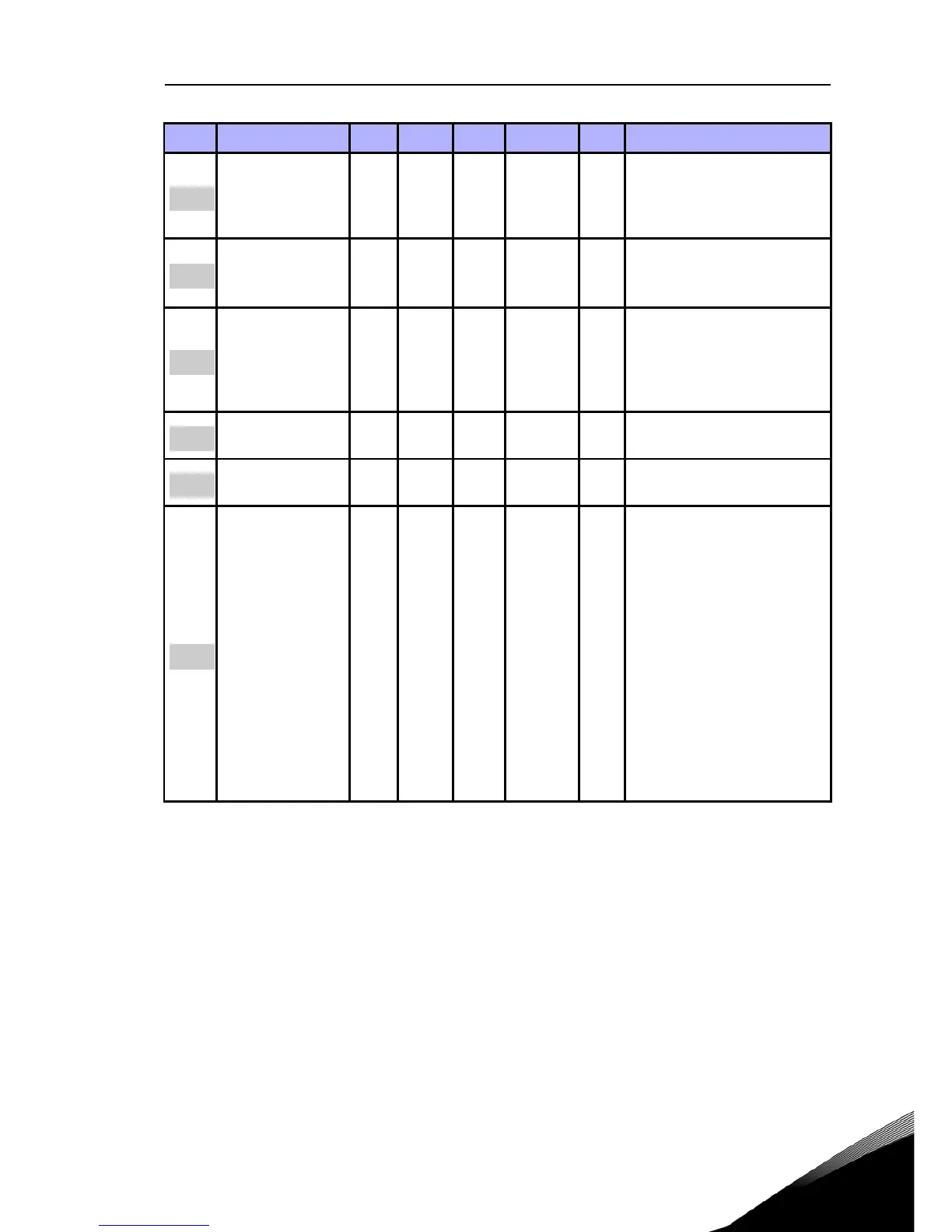
Code Parameter Min Max Unit Default ID Note
Table 5.3: Motor settings
 Loading...


