monitoring & parameters vacon • 19
24-hour support +358 (0)201 212 575 • Email: vacon@vacon.com
5
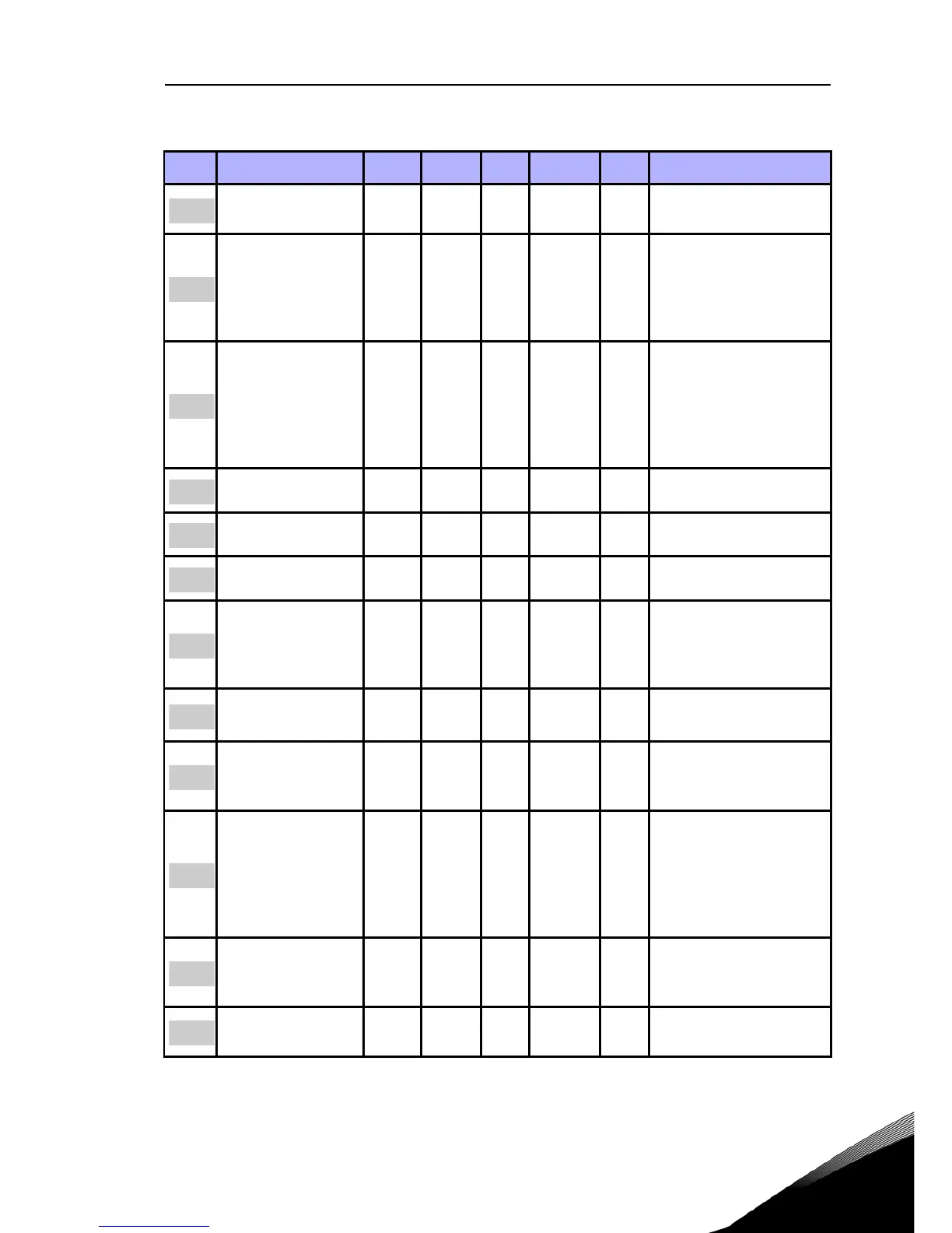
5.6 Ramps and brakes setup (Control panel: Menu PAR -> P4)
Code Parameter Min Max Unit Default ID Note
Ramp S-shape 0,0 10,0 s 0,0 500
0 = Linear
>0 = S-curve ramp time
Acceleration time 1 0,1 3000,0 s 3,0 103
Defines the time
required for the output
frequency to increase
from zero frequency to
maximum frequency
Deceleration time 1 0,1 3000,0 s 3,0 104
Defines the time
required for the output
frequency to decrease
from maximum fre-
quency to zero fre-
quency
Ramp S-shape 2 0,0 10,0 s 0,0 501 See the parameter P4.1
Acceleration time 2 0,1 3000,0 s 10,0 502 See the parameter P4.2
Deceleration time 2 0,1 3000,0 s 10,0 503 See the parameter P4.3
Flux Braking 0 3 0 520
0 = Off
1 = Deceleration
2 = Chopper
3 = Full Mode
Flux Braking Cur-
rent
0,5 x
I
Nunit
2,0 x
I
Nunit
A
I
Nunit
519
DC Braking Current
0,3 x
I
Nunit
2,0 x
I
Nunit
A
I
Nunit
507
Defines the current
injected into the motor
during DC brakeing
Stop DC current
time
0,00 600,00 s 0,00 508
Determines if braking is
ON or OFF and the brak-
ing time of the DC-brake
when the motor is stop-
ping
0 = Not active
Stop DC current
frequency
0,10 10,00 Hz 1,50 515
The output frequency at
which the DC-braking is
applied
Start DC current
time
0,00 600,00 s 0,00 516 0 = Not active
Table 5.6: Ramps and brakes setup
 Loading...


