Installation vacon • 9
Local contacts: http://drives.danfoss.com/danfoss-drives/local-contacts/
4
4
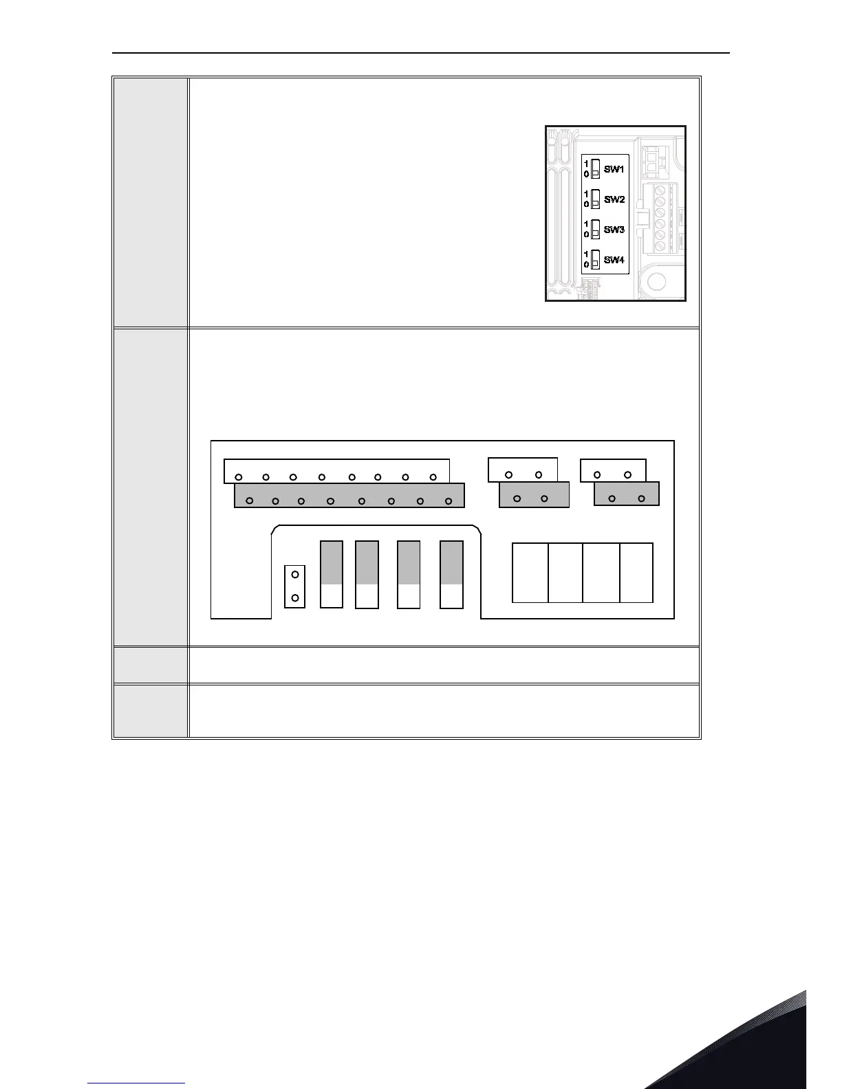
NOTE! This step is valid only for VACON
®
20 CP and VACON
®
20 X.
If VACON
®
20 Cold Plate drive is the last device on
the bus, the bus termination must be set. Locate the
switches to the right of the control terminals and turn
the SW4 switch to position “0”. Biasing is built in the
termination resistor.
5
NOTE! This step is valid only for VACON
®
20.
The RS-485 bus is terminated with termination resistors of 120 ohms in both
ends. VACON
®
20 has a built-in termination resistor which is switched off as a
default (presented below). The termination resistor can be switched on and off
with the right hand dip switch located above IO-terminals in the front of the drive
(see below). Biasing is built in the termination resistor.
6
NOTE: When planning the cable runs, remember to keep the distance between
the fieldbus cable and the motor cable at a minimum of 30 cm.
7
The bus termination must be set for the first and the last device of the fieldbus
line. We recommend that the first device terminated is the Master device.

 Loading...


