4
vacon • 8 Installation
Local contacts: http://drives.danfoss.com/danfoss-drives/local-contacts/
4. INSTALLATION
4.1 Installation in VACON
®
20 family AC drives
The connection for RS485 is on the standard I/O terminals (A and B). See VACON
®
20 or VACON
®
20
X /CP Installation Manual depending on the drive you are using.
4.1.1 Preparation for use through RS485
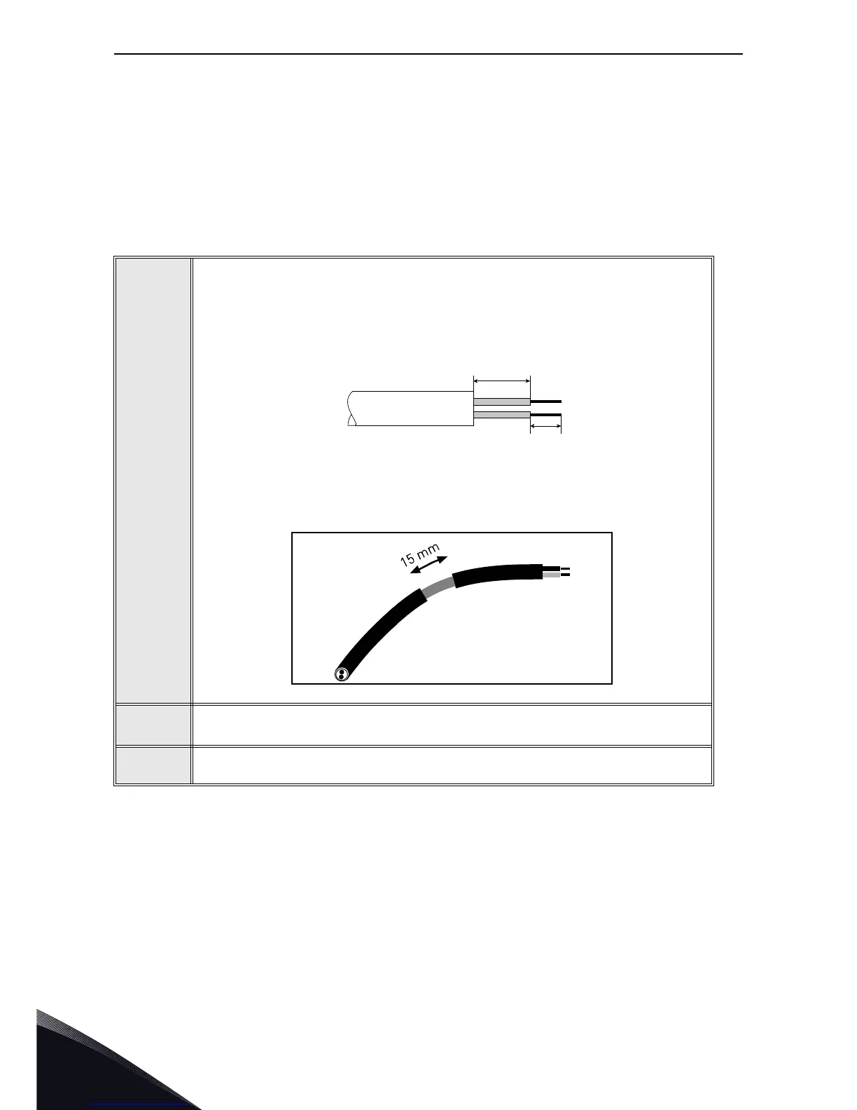
1
Strip about 15 mm of the RS485 cable and cut off the grey cable shield. Remem-
ber to do this for both bus cables (except for the last device).
Leave no more than 10 mm of the cable outside the terminal block and strip the
cables at about 5 mm to fit in the terminals. See picture below.
Also strip the cable now at such a distance from the terminal that you can fix it to
the frame with the grounding clamp. Strip the cable at a maximum length of 15
mm. Do not strip the aluminium cable shield!
2
Then connect the cable to its appropriate terminals on VACON
®
20 CP AC drive
standard terminal block, terminals A and B (A = negative, B = positive).
3
Using the cable clamp included in the supply of the drive, ground the shield of
the RS485 cable to the frame of the AC drive.

 Loading...


