7
vacon • 22 Fault tracing
Local contacts: http://drives.danfoss.com/danfoss-drives/local-contacts/
7. FAULT TRACING
When an unusual operating condition is detected by the AC drive control diagnostics, the drive ini-
tiates a notification visible, for example, on the keypad. The keypad will show the ordinal number of
the fault, the fault code.
The fault can be reset with the Reset button on the control keypad or via the I/O terminal. The faults
are stored in the Fault history menu which can be browsed. The different fault codes you will find
in the table below. This fault table presents only the faults related to the fieldbus in use.
NOTE! When contacting distributor or factory because of a fault condition, always write down all
texts and codes on the keypad display and send a description of the problem together with the
Drive
Info File
to your local support.
7.1 Typical fault conditions
7.2 RS-485 bus biasing
When none of the devices on the RS-485 bus is sending data, all devices are in idle status. This being
the case, the bus voltage is in indefinite state, usually near 0 V due to the termination resistors. This
may cause problems in character reception because the single characters in serial communication
begin with start bit referring to bus status '0' with voltage of less than -200mV whereas the bus sta-
tus '1' corresponds to bus voltage of more than +200mV. The RS-485 standard considers the voltage
interval -200mV...+200mV as undefined state. Bus biasing is therefore needed to maintain the volt-
age in status ‘1’ (above +200mV) also between the messages.
By activating the line termination using the dedicated dip switch described in Chapter 4.1.1, also a
560 Ohm resistor for line polarization is activated.
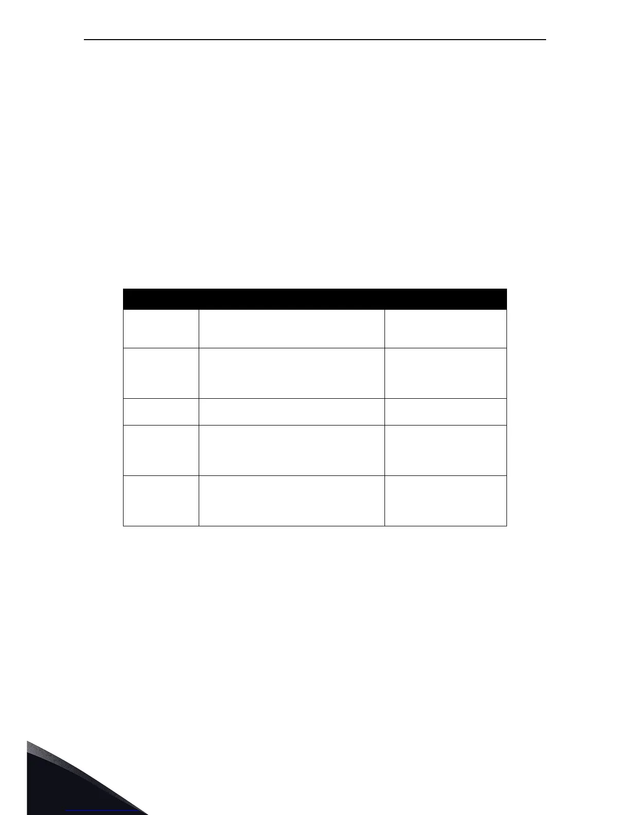
Table 24. Typical fault conditions
Fault condition Possible cause Remedy
Termination
resistor
Missing or excessive termination resistor.
Install termination resis-
tors at both ends of the
fieldbus line.
Cabling
• Supply or motor cables are located
too close to the fieldbus cable
• Wrong type of fieldbus cable
• Too long cabling
Grounding Inadequate grounding.
Ensure grounding in all
points on the net
Connections
Faulty connections.
• Excessive stripping of cables
• Conductors in wrong terminals
• Too loose connections of conductors
Parameter
• Faulty address
• Overlapping slave addresses
• Wrong baud rate
• Wrong control place selected

 Loading...


