Communications vacon • 19
Local contacts: http://drives.danfoss.com/danfoss-drives/local-contacts/
6
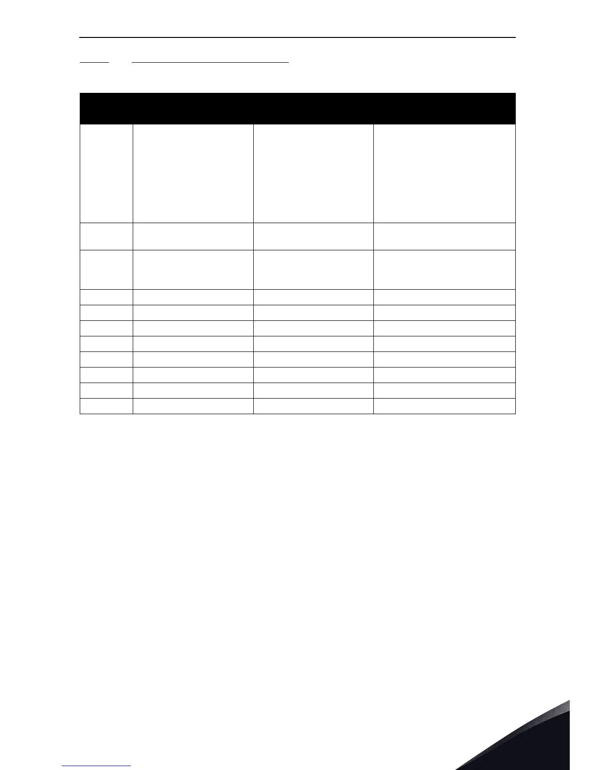
6.3.2.2 Fieldbus Data OUT: Slave -> Master
Table 15.
Modbus
Register
Name Description Range
2101 Status word Drive state
Binary coded:
b0: Ready
b1: Run
b2: Reverse
b3: Fault
b4: Warning
b5: Freq. reference reached
b6: Zero speed
2102 General Status word Drive state
As Status word and:
b7: Control place is fieldbus
2103 Actual speed Actual speed
0...10000 as 0.00...100.00%
of Min freq. - Max freq.
range
2104 Fieldbus Data OUT 1 Programmable See P11.1
2105 Fieldbus Data OUT 2 Programmable See P11.2
2106 Fieldbus Data OUT 3 Programmable See P11.3
2107 Fieldbus Data OUT 4 Programmable See P11.4
2108 Fieldbus Data OUT 5 Programmable See P11.5
2109 Fieldbus Data OUT 6 Programmable See P11.6
2110 Fieldbus Data OUT 7 Programmable See P11.7
2111 Fieldbus Data OUT 8 Programmable See P11.8

 Loading...


