Troubleshooting
ecoTEC plus installation and maintenance instructions 0020134823_01 57
14
14.2.4 Calling up diagnostics levels
Menu ¬ Installer level ¬ Diagnostics menu
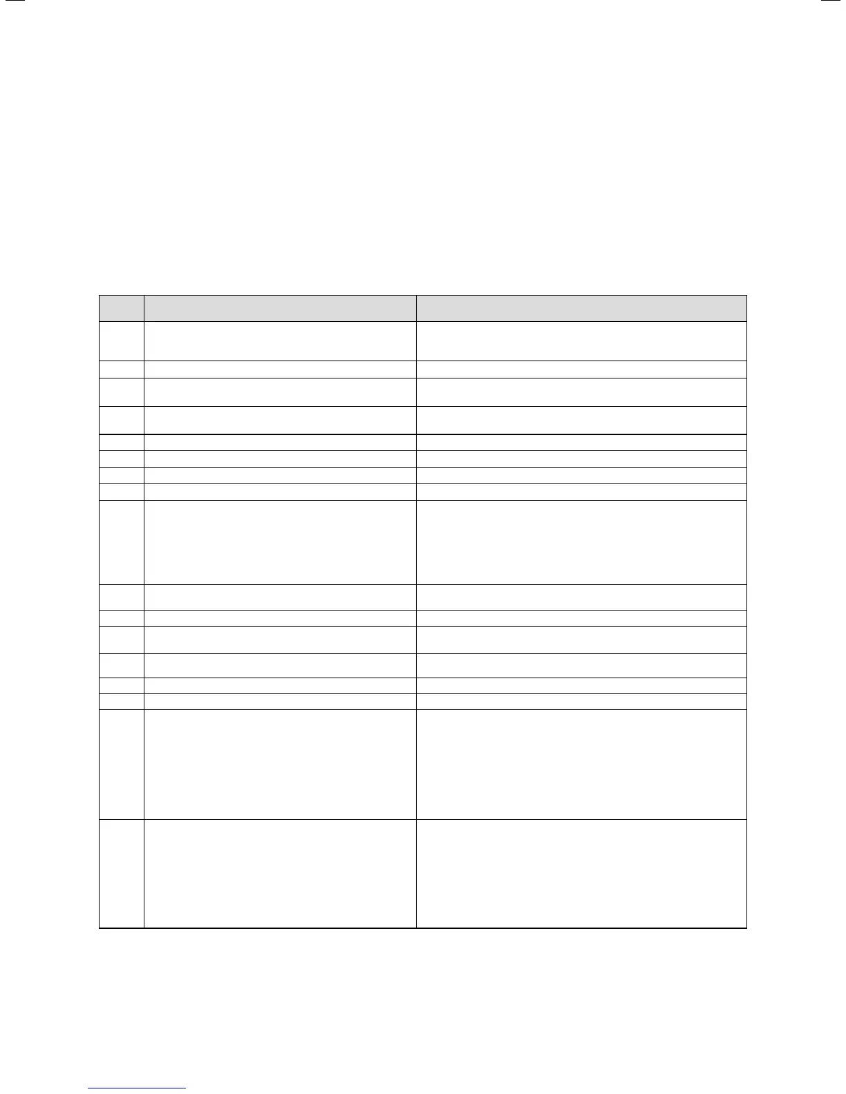
You can use the diagnostics menu to inspect parameters
and modify certain parameters. An overview of all diagnos-
tics codes can be found in ¬table12.1.
14.2.5 Overview of diagnostics codes at installer
level
Display Meaning Display value/adjustable value
D.000 Heating partial load Adjustable heating partial load in kW
(Factory setting: auto: Unit automatically adjusts max. partial load to
current system demand)
D.001 Pump overrun for heating mode 2 - 60 minutes (factory setting: 5)
D.002 Max. burner anti-cycling time heating at 20 °C flow
temperature
2 - 60 minutes (factory setting: 20)
D.005 Flow temperature target value (or return target value) In °C, max. of the value set in D.071, limited by an eBUS controller if
connected
D.006 Hot water temperature target value 35 to 65 °C
D.007 Warm start temperature target value 40 to 65 °C
D.010 Heating pump status of the pump group 1 = on, 0 = off
D.011 Status of external heating pump 1 to 100 = on, 0 = off
D.014 Target value for pump speed Heating circuit pump target value in %
0 = auto (default setting)
1 = 53
2 = 60
3 = 70
4 = 85
5 = 100
D.016 Room thermostat 24 V DC at terminal 3'-4‘ (only NL) 0 = Room thermostat open (no heating mode)
1 = Room thermostat closed (heating mode)
D.017 Heating flow/return regulation changeover 0 = flow, 1 = return (default setting: 0)
D.018 Pump operating mode setting 1 = Comfort (continuously operating pump)
3 = Eco (intermittently operating pump, default setting)
D.022 Hot water demand via C1/C2, internal hot water control
system
1 = on, 0 = off
D.023 Summer/winter operating mode (heating on/off) 1 = Heating on, 0 = Heating off (summer mode)
D.025 Hot water generation enabled by eBUS controller 1 = Yes, 0 = No
D.027 Switching of relay 1 on the
"2 in 7" multi-functional module VR 40
1 = Circulation pump (default setting)
2 = Ext. pump
3 = Charging pump
4 = Extractor hood
5 = Ext. solenoid valve
6 = Ext. error message
7 = Not active
8 = Remote control eBUS (not active)
9 = Anti-legionella pump (not active)
D.028 Switch of relay 2 on the "2 from 7" multi-functional
module VR 40
1 = Circulation pump
2 = Ext. pump (factory setting)
3 = Charging pump
4 = Extractor hood
5 = Ext. solenoid valve
6 = Ext. error message
7 = Not active
8 = Remote control eBUS (not active)
9 = Anti-legionella pump (not active)
14.2 Diagnostics codes at installer level