Appendix
122 Installation instructions geoTHERM 0020051574_04
17
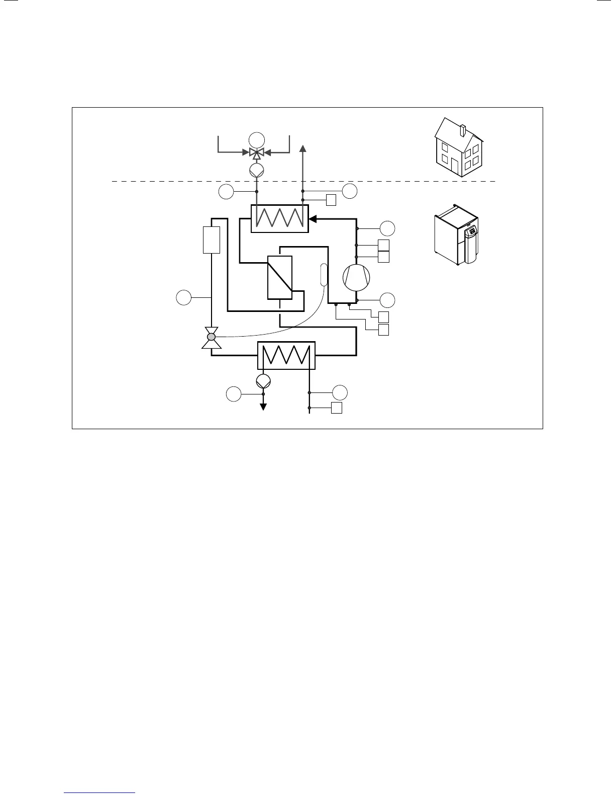
Heat pump schematic - VWS
9
13
5
12
11
17 16 15
1
M
3
6
7
2
4
8
T5
T4
T1
T2
T3
T8
T6
10
14
17.1 Appendix, Heat pump scheme VWS ..0/2
Key
1 Heating supply line
2 Heating circuit pressure sensor
3 High pressure sensor
4 High pressure switch
5 Compressor
6 Low pressure sensor
7 Low pressure switch
8 Brine circuit pressure sensor
9 Evaporator
10 Brine circuit pump
11 Expansion valve
12 Filter drier
13 Condenser
14 heating circuit pump (to be fitted on-site)
15 Heating return line
16 3-way heating/cylinder charging diverter valve
(to be fitted on-site)
17 DHW return line

 Loading...


