Hydraulics installation
36 Installation instructions geoTHERM 0020051574_04
5
b
Caution!
Risk of malfunction!
Dirt filters may lead to flow rate problems
and a reduction in the residual pump head
for the brine pump.
> Do not install dirt filters for a prolonged
period in the brine circuit. The brine fluid
is cleaned during the filling process.
b
Caution!
Risk of damage caused by the formation
of condensation.
Condensation on uninsulated brine pipe-
lines within the building may lead to struc-
tural damage.
> You must insulate all brine pipelines
using vapour diffusion-tight insulation.
> Fit the brine pipelines between the heat source and the
heat pump along with all the associated components in
accordance with the applicable technical guidelines.
i
To prevent freezing, use cold pipe clips to con-
nect the brine pipelines to the heat pump.
> Connect the brine pipelines to the heat pump (3) and (4)
(¬Fig.5.8).
> Insulate all pipelines using vapour diffusion-tight insula-
tion.
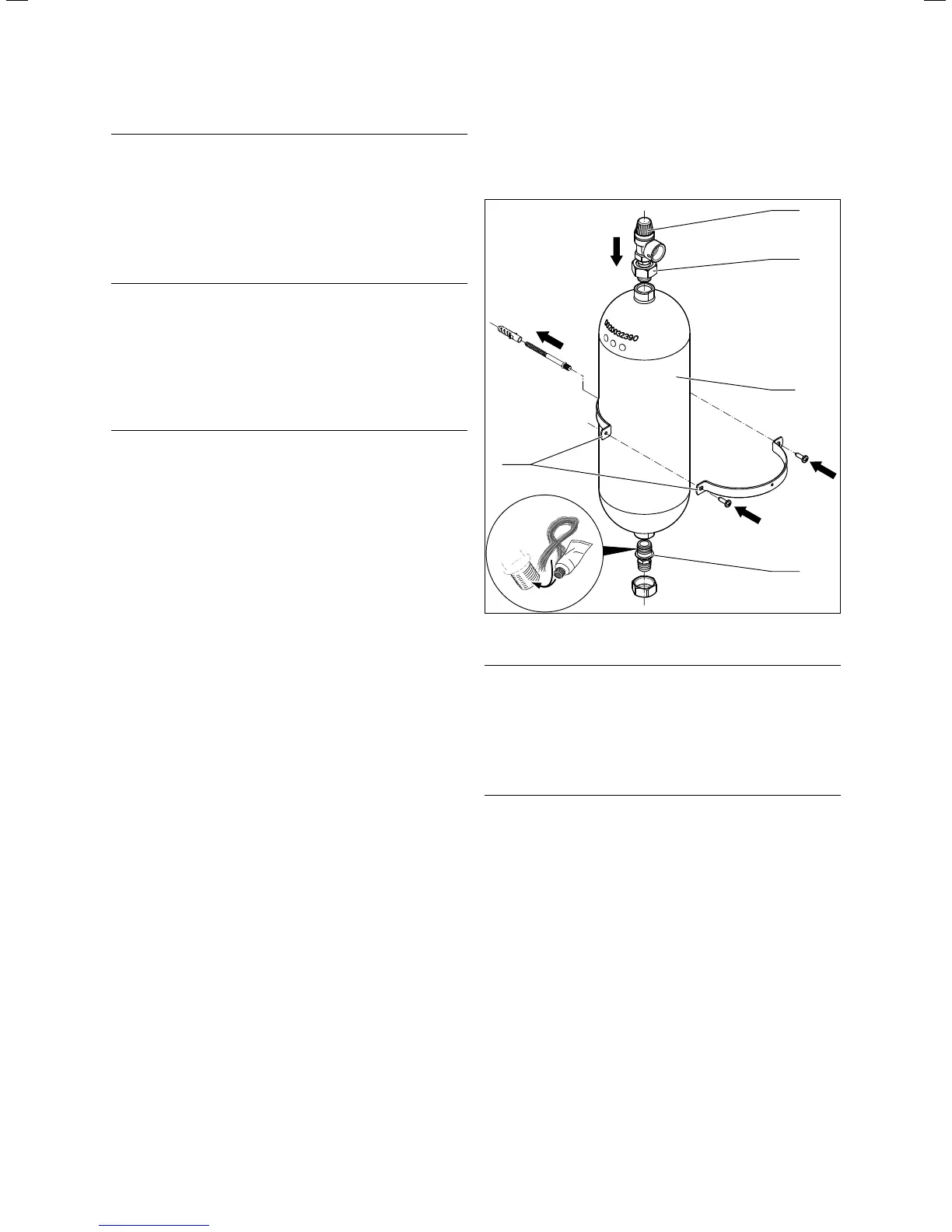
5.9 Fitting the brine expansion tank in the
brine circuit (VWS only)
42a
1
2
57
3
5.10 Fitting the brine expansion tank
b
Caution!
Risk of damage from escaping brine.
If the lower screw coupling on the brine
expansion tank (2) has been sealed using
Teflon tape or something similar, this may
lead to leaks in the brine circuit.
> Seal this screw coupling with hemp.
i
The brine expansion tank from the accessories
has a volume of approx. 6 litres and is therefore
adequate for brine circuits up to a maximum of
500 litres. For larger volumes, other expansion
tanks that are fitted on-site must be installed.
> Use the dowel and the screw to fit the bracket (3) for the
expansion tank to the wall.
> Unscrew the prefitted connecting pieces (1 and 2) from
the brine expansion tank (57).
> Put hemp on the outside thread of the lower connecting
piece.
> Install the brine expansion tank with the lower connect-
ing piece in the pipeline from the heat source to the heat
pump.

 Loading...


