6 Installation instructions - Interface 0-10 V VR 34 0020017083_02
3.3 Application
The Vaillant VR 34 0-10 V interface is used
when a BEMS system is to be connected to a
Vaillant boiler with an eBUS interface. It con-
verts the voltage applied to the "I" terminal
into a temperature target value for the boiler.
Terminal "F" can be used to signal an error in
the boiler (24 V). The error signal persists
until the error has been removed and the
boiler has been reset. A 24 V relay drawing a
maximum current of 30 mA can be connected
between the "F" terminal and "24 V".
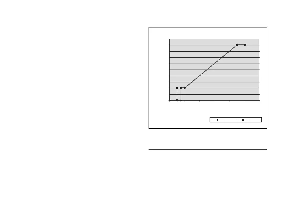
Curve 10 V-Modul
0
10
20
30
40
50
60
70
80
90
100
024681012
Input voltage
flow temperature setpoint [°C]
up
down
Fig. 3.1 Characteristic of 0-10 V interface
h
Note
The chassis terminal is at earth po-
tential.
3 Description of the appliance