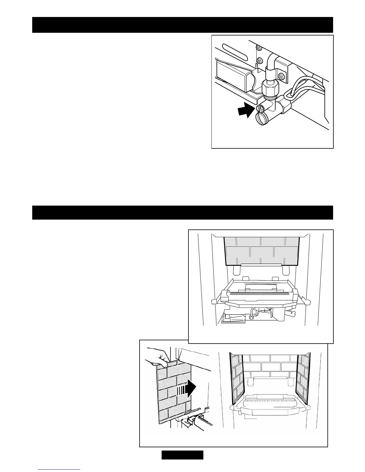
10.3 Inlet pressure check.
The appliance is pre-set to give the correct heat
input at the inlet pressure shown in section 2 of
this manual. No adjustment is necessary.
1. Ensure that the appliance is switched OFF, then
fit a pressure gauge at the test point. The test
point is on the inlet ‘T’ connector (See figure 25).
Check the pressure with the appliance alight and
set at maximum output.
2. After checking, turn off the appliance. Remove
the pressure gauge and replace the test point
sealing screw.
3. Light the appliance. Turn to the maximum output
position and test around the sealing screw for gas soundness with a suitable leak
detection fluid.
When the above checks from section 10.2 and 10.3 have been completed close
the isolating valve on the inlet ‘T’ connector.
11. CERAMIC WALLS INSTALLATION
1. Fit the ceramic rear wall inside the “U”
bracket on the back face of the burner
compartment. Push the ceramic wall flat
against the back face of the burner
compartment (See figure 26).
2. Fit the ceramic side walls against the side
faces of the burner compartment. The
bottom edges of the walls should rest in the
ledges at the sides of the firebox. Slide
them in from the front and ensure that they
touch the rear wall. Be careful not to
damage the edges of the side
walls (See figure 27).
Page 31
© Baxi Heating U.K. Limited 2009.
INSTALLER GUIDE
Figure 25. Pressure test point
Figure 27. Ceramic side walls installation
Figure 26.