should be drilled within the range of positions shown in figure 21 using a suitably
sized masonry drill bit for the wall plugs supplied. The holes should be equidistant
each side of the centre line of the fireplace to ensure that the appliance finishes
centrally in the opening when tension is applied to the cables.
3. Insert a fibre / wooden plug into each hole. Use the fibre / wooden plugs supplied
with this appliance - Never use plastic plugs instead of the fibre / wooden plugs
supplied. Screw the eyebolts into the plugs. Make
sure that the bolts are secure.
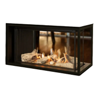
4. Place the convection box unit close to the fireplace
but allow sufficient access into the fireplace opening so
that the cables can be threaded through the eyebolts
and returned through the back of the convection box. If
a concealed connection is being used, insert the
convection box into the fireplace feeding the supply
pipe through the pierced hole in the rear grommet.
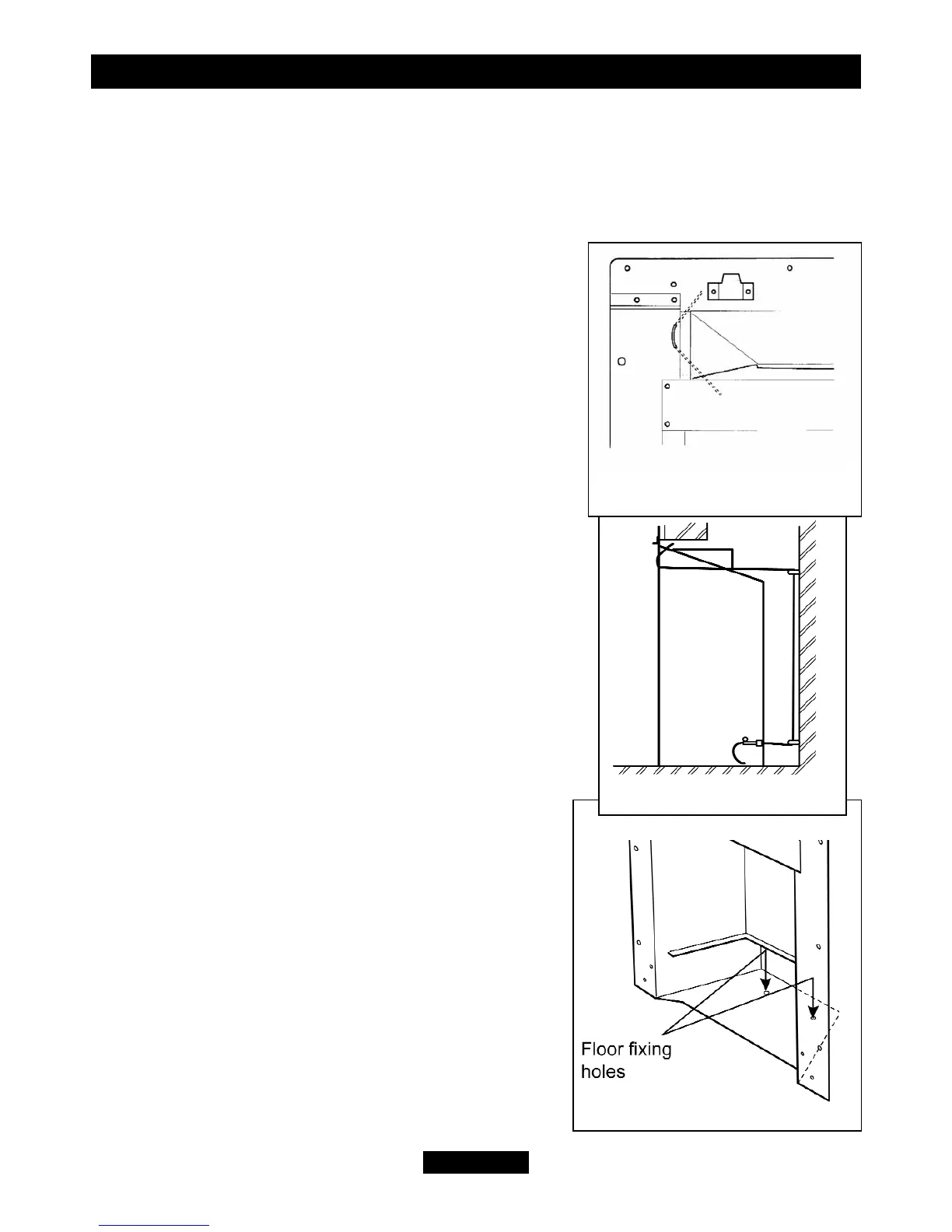
5. The convection box has two holes at each side of
the convected air opening. Insert one end of each
cable (one cable each side) from the back through the
lower of the two holes and return the end through the
upper of the holes (See figure 22). Give the cables a
pull so that they grip against the convection box flanges.
6. Thread the cables through the eyebolts. Return the
cables through the holes near the bottom of the
convection box back panel (See figure 23) (For precast
or clay block flue systems return the cables through
the slotted holes in the side of the convection box).
7. Place the convection box fully back into the fireplace
opening so that it is sealed against the fireplace front
surround.
8. Drill a hole into the fireplace floor through each of
the two holes in the base of the convection box using
a using a suitably sized masonry drill bit for the wall
plugs supplied (See figure 24).
9. Insert a fibre/ wooden plug into each hole. Use the
fibre / wooden plugs supplied with this appliance -
Never use plastic plugs instead of the fibre /
wooden plugs supplied. Fit a woodscrew in each
plug and tighten.
Always screw the base into position before
applying tension to the cables. This will ensure a
tight seal between the top of the convection box
and wall.
© GDC Group Ltd. 2011
Page 27
INSTALLER GUIDE
Figure 24. Floor fixing
Figure 23. Cable route
Figure 22. Upper cable
retention