12
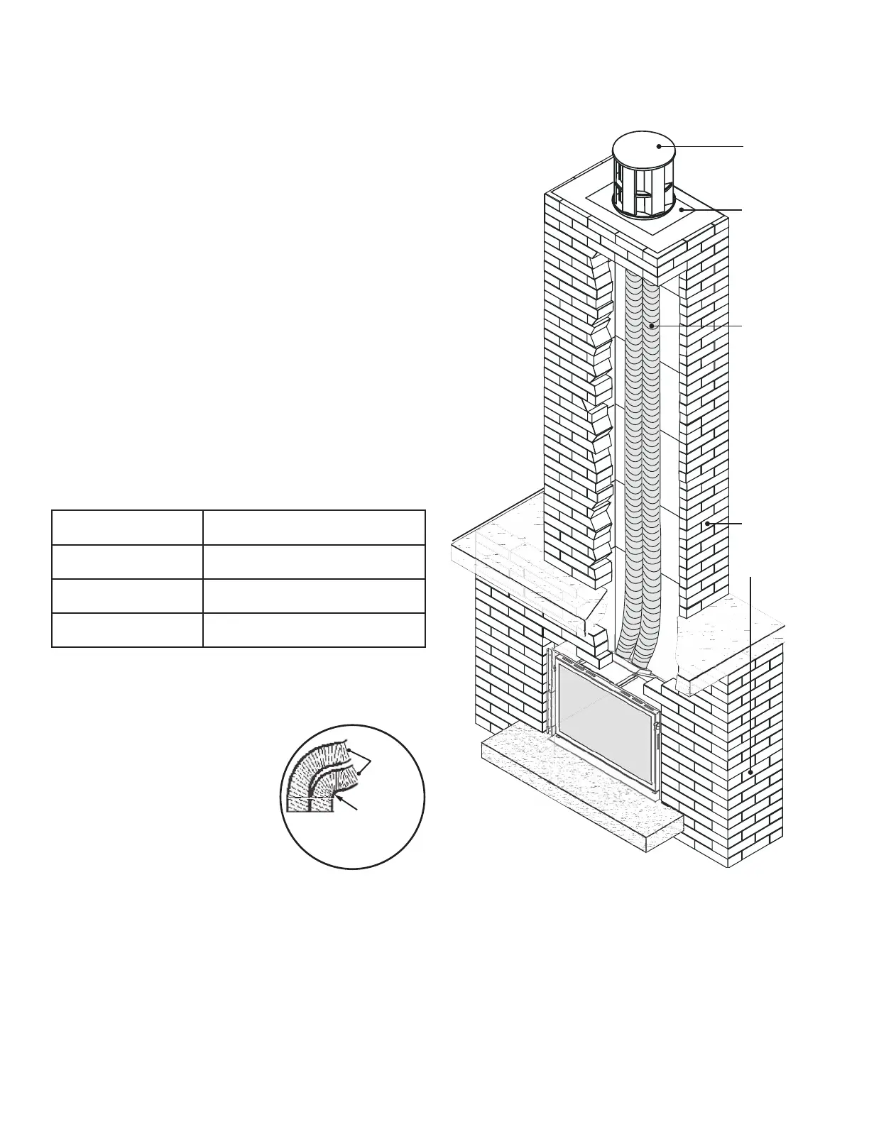
Typical Vent Installation
NOTE: Flexible co-linear vent pipes may only be
installed into existing non-combustible solid-fuel
burning replaces and chimneys.
See list of approved Venting Accessories on page 41 of
this manual. The appliance must not be connected to
a chimney fl ue serving a separate solid-fuel burning
appliance.
The required fi replace dimensions and clearances are
shown in Dimensions (page 8) and Clearances (page
9) sections of this manual.
Vent Location
The vent terminal must be located through the roof. This
direct vent appliance is designed to operate when an
undisturbed airfl ow hits the outside vent terminal from
any direction.
Check local codes for allowable vertical vent termination.
Venting Table
Maximum vertical height 40 ft (measured to bottom of
termination)
Minimum vertical height 10 ft (measured to bottom of
termination)
Maximum horizontal run 4 ft (measured center to center of
pipe)
Maximum o set angle 45˚ (sweeping bend to allow for
obstructions)
Venting Notes
Where possible, avoid joining fl ex pipes. If joints are
required, use a approved connector and seal joints with
RTV high temp sealant.
Horizontal off set is permissible to
allow for routing around masonry
projections. Avoid bending fl ex
pipe over a 45 degrees radius
where possible.
Terminal Cap
Flashing
2 x 3” ex
liners—see
Venting
Table for
length
allowed
Existing
replace
and
chimney
Venting
Concept
3” Liners
3” min.
Bend
Radius
 Loading...