VAMP 135 Over-, under-, residual voltage and
frequency relay
Technical description
VAMP Ltd
6
VAMP 24h support phone : +358 (0)20 753 3264
VM135.EN008
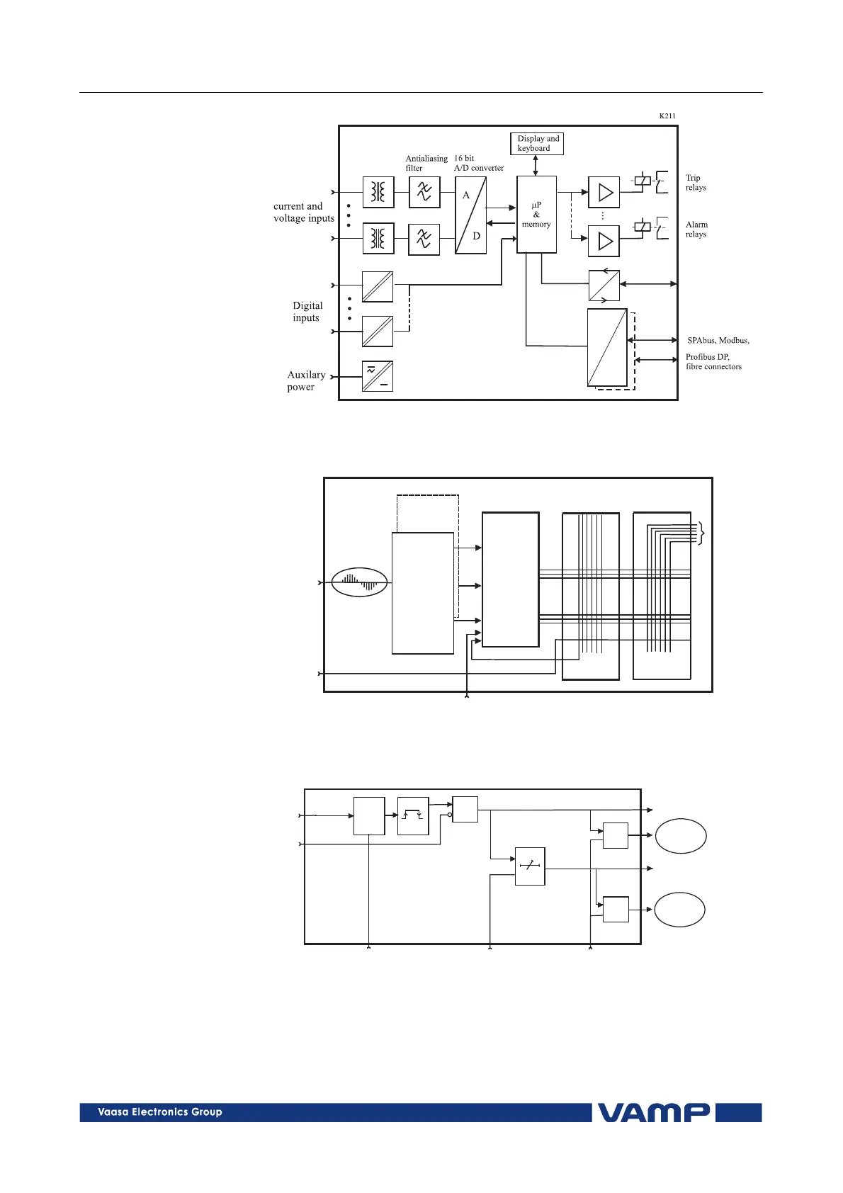
Figure 2.1-1 Principle block diagram of a numerical protection relay.
Im
Um
U
2 samples/cycle
n
Digital
input
Settings
Amplitudeand
phaseshiftof
basefreqency
component
FFTcalculation
Calculationof
symmetric
components
Protection
functions
Trip
start
Block
Blockmatrix
Outputmatrix
Outputrelay
control
K212vamp135
Figure 2.1-2 Block diagram of a software based protection relay.
ts
tr
&
t
&
&
U
1VUSLOHKO
>
Blocking
Setting
U>s
Delay
Enable
event
Start
Event
register
Trip
Event
register
Figure 2.1-3 Block diagram of a single-phase protection function.