VAMP 135 Over-, under-, residual voltage and
frequency relay
Technical description
VAMP Ltd
20
VAMP 24h support phone : +358 (0)20 753 3264
VM135.EN008
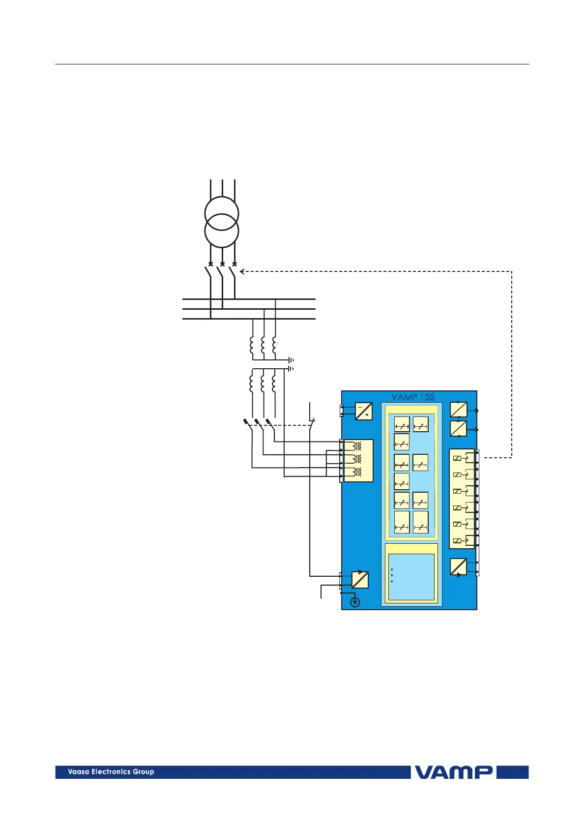
3. Application examples
3.1. Feeder over-, under- and residual
voltage protection (3Phase mode)
2
1
2
4
6
19
12
1
3
5
20
11
17
16
14
13
9
12
8
11
7
10
X1
X1
X2
X2
5
4
-
+
U
mA
VAMP135
BI
T1
T2
A1
A2
A3
IF
Protectionfunction
~
Measurement
functions
U ,U ,U
L1 L2 L3
U ,U ,U
12 23 31
U ,U ,U
0 1 2
U
L1
U
L2
U
L3
f>,
f>>
f<,
f<<
Uo> Uo>>
U>>>
U<<<
U>
U>>
U< U<<
vamp135appl1
Figure 3.1-1. Three-phase overvoltage, undervoltage and residual voltage
protection of a feeder. The voltage measurement mode is set to “3Phase”
The relay is connected to the phase voltages U
L1
, U
L2
and U
L3
.
The residual voltage is calculated from the measured phase
voltages. The digital input (DI) can be used for blocking of the
residual voltage stages. The digital input is controlled by the
auxiliary contact of the contactor’s secondary measuring
circuit.