VAMP 135 Over-, under-, residual voltage and
frequency relay
Technical description
VAMP Ltd
18
VAMP 24h support phone : +358 (0)20 753 3264
VM135.EN008
Profibus connection (VPA 3CG). Please see the corresponding
documentation for more details.
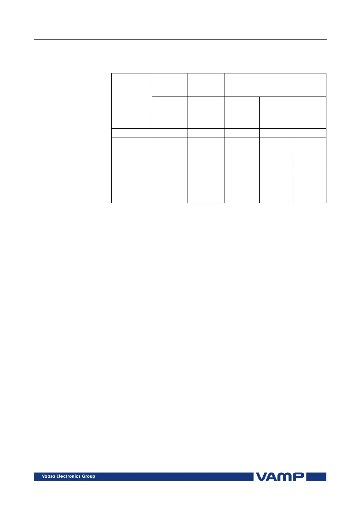
Standard
interface
Internal
option
cards
External option modules
Protocol RS232:
VX004-M3
or
VX008-4
Plastic
fibre:
RS485:
VSE 002
ProfiBus:
VPA3CG
+
VX007-F3
Ethernet:
VEA3CG
+
VX015-3
ModBus X X X
SPA-Bus X X X
ProfiBus X
IEC-60870-
5-103
X X X
ModBus/
TCP
X
Transparent
TCP/IP
X
Table 2.6.2-1 Communication protocols and physical interfaces on REMOTE
serial port.
2.7. Disturbance recorder
The disturbance recorder can be used to record all measured
signals i.e. currents and voltages, status information of digital
inputs (DI) and digital outputs (DO). The digital inputs include
also the Arc light information (S1, S2 and Arc binary input BI).
The digital outputs include the Arc binary output information
(BO).
Recorder capacity is 48 000 bytes. There can be a maximum of
5 recordings and the maximum selection of channels in one
recording is 12 (limited in waveform recording).
The recorder can be triggered by any protection stage start or
trip signal, Arc sensors (S1, S2, BI) and digital input. The trig
signal is selected in the output matrix. The recording can also
be triggered manually.
When recording is made also the time stamp will be
memorized.
The recordings can be viewed by VAMPSET program, version
8.x or newer. The recording is in COMTRADE format so also
other programs can be used to view the recordings.
For more detailed information, see separate Disturbance
Recorder manual VMDR.EN0xx.