VAMP 135 Over-, under-, residual voltage and
frequency relay
Technical description
VAMP Ltd
12
VAMP 24h support phone : +358 (0)20 753 3264
VM135.EN008
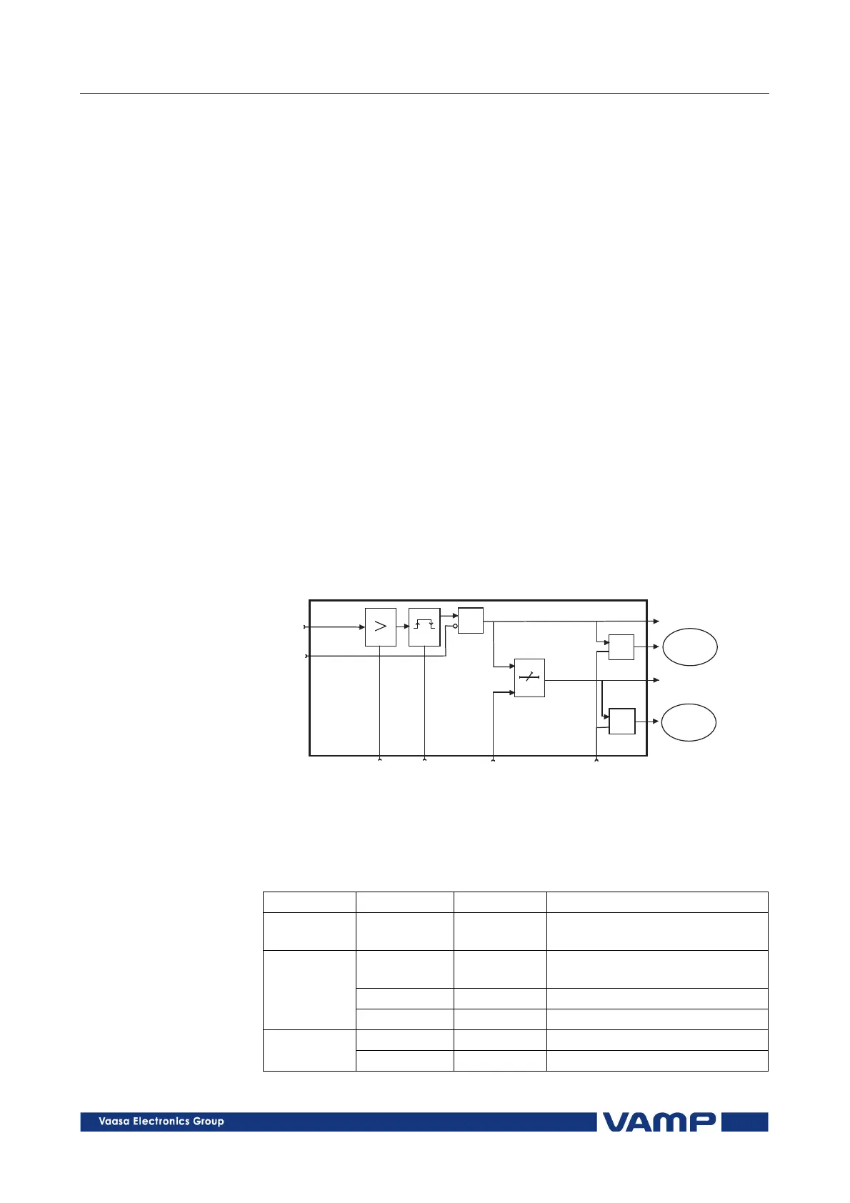
2.3.3. Residual voltage protection U
0
>, U
0
>> (59N)
The residual voltage unit comprises two separately adjustable
residual voltage stages (stage U
0
> and U
0
>>).
The undervoltage unit measures the fundamental frequency
component of the residual voltage, which means that the
harmonics will not cause a trip. The protection stages operate
with definite time characteristics.
The relay starts, if the actual value for the residual voltage
exceeds the setting value. If the overvoltage situation continues
after the start time has elapsed, the relay trips.
The residual voltage is measured either with a residual voltage
transformer or calculated from the phase voltages according to
the selected protection mode:
•
Phase: The residual voltage is calculated from the phase
voltages and therefore a separate residual voltage
transformer is not needed. The setting values are relative to
the voltage VT
secondary
defined at configuration.
•
Line+U
0
: The residual voltage is measured with an broken-
delta transformer. The setting values are relative to the
voltage VT
0secondary
defined at configuration.
•
Line: The residual voltage functions are not in use.
&
t
&
&
Uo
u0slohko
ts
tr
Setting
Uo>s
Delay Enable
events
Start
Trip
Event
register
Blocking
Event
register
Release
delay
Figure 2.3.3-1. Block diagram of the residual voltage stages U
0
> and U
0
>>.
Parameters of the residual voltage protection stages:
U
UU
U
0
00
0
>, U
>, U>, U
>, U
0
00
0
>> (59N)
>> (59N)>> (59N)
>> (59N)
Parameter
ParameterParameter
Parameter
Value/unit
Value/unitValue/unit
Value/unit
Measured
value
U
0
>, U
0
>> V Residual voltage U
0
as
primary value
U
0
>, U
0
>> % Setting value in relation to the
rated voltage U
0
n
t>, t>> s Operation time
Setting
values
ReleaseDly s Release delay (only U
0
>)
SCntr Start counter (Start) reading Recorded
values
TCntr Trip counter (Trip) reading