VAMP 135 Over-, under-, residual voltage and
frequency relay
Technical description
VAMP Ltd
10
VAMP 24h support phone : +358 (0)20 753 3264
VM135.EN008
Overvoltagefault
U>start
U>>start
U>trip
U>>trip
ALARM
TRIP
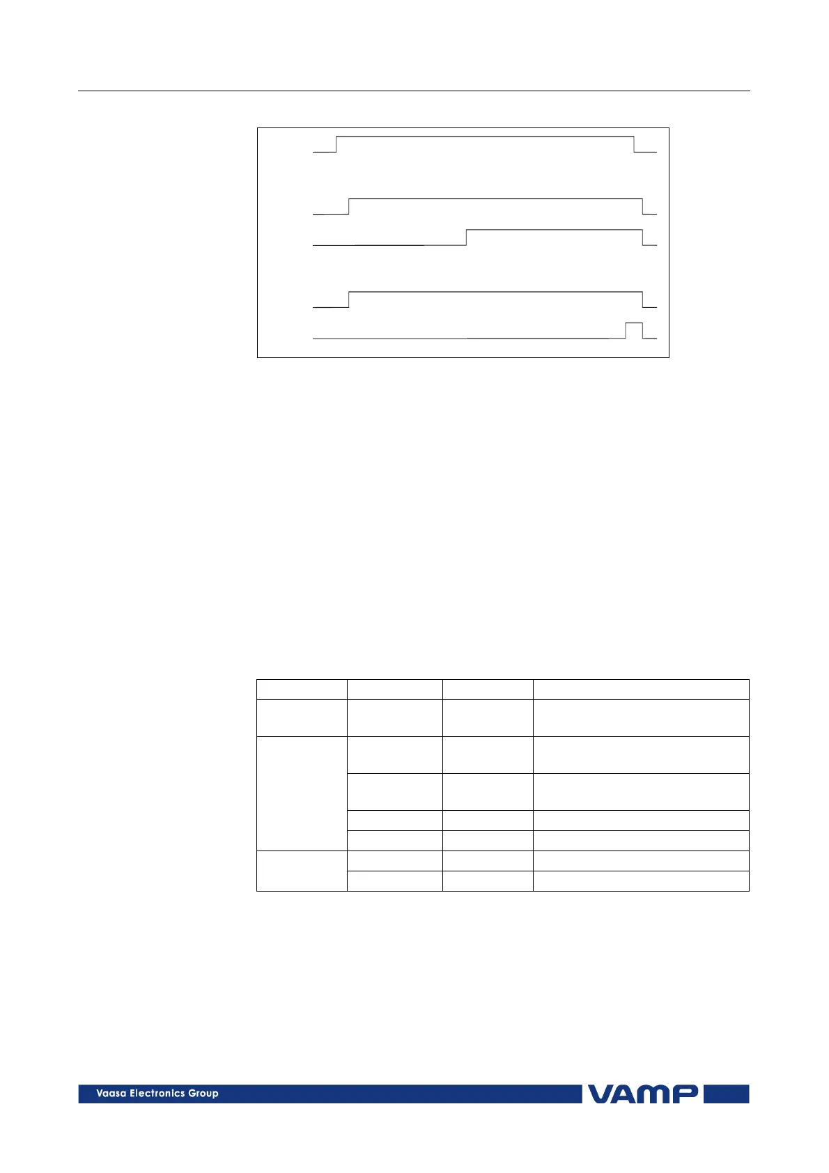
Figure 2.3.1-3. A settable start time is obtained by combining two protection
stages.
A settable start time is obtained by combining two protection
stages. Both stages detect the overvoltage, but the start signals
are ignored. The trip signal of stage U> is used as an alarm
signal and trip information from stage U>> is used for the
actual trip. The overvoltage setting value for stage U>> has to
be higher than the setting value for stage U> to ensure an
alarm before trip.
During a short circuit or an earth-fault, breaker Q1 performs
an auto-reclose. Breaker Q2 has to be tripped before the auto-
reclose of breaker Q1 to ensure that the generator does not
continue to feed the fault.
Parameters of the overvoltage stages: U>, U>>, U>>> (59)
Parameter
ParameterParameter
Parameter
Va
VaVa
Value/unit
lue/unitlue/unit
lue/unit
Measured
value
U>, U>>,
U>>>
V Max. value of line voltages
U12 to U31 primary values
U>, U>>,
U>>>
% Setting value in relation to the
rated voltage Un
t>, t>>,
t>>>
s Operation time
ReleaseDly s Release delay [s] (only U>)
Setting
values
Hysteresis % Deadband (only U>)
SCntr Start counter (Start) reading Recorded
values
TCntr Trip counter (Trip) reading
2.3.2. Undervoltage protection U<, U<<, U<<< (27)
The three-phase undervoltage unit comprises three separately
adjustable undervoltage stages (stage U<, U<< and U<<<).
The undervoltage unit measures the fundamental frequency
component of the line voltages. The protection stages operate
with definite time characteristics.