VAMP Ltd
Over-, under-, residual voltage and
frequency relay
Technical description
VAMP 135
VM135.EN008 VAMP 24h support phone : +358 (0)20 753 3264
9
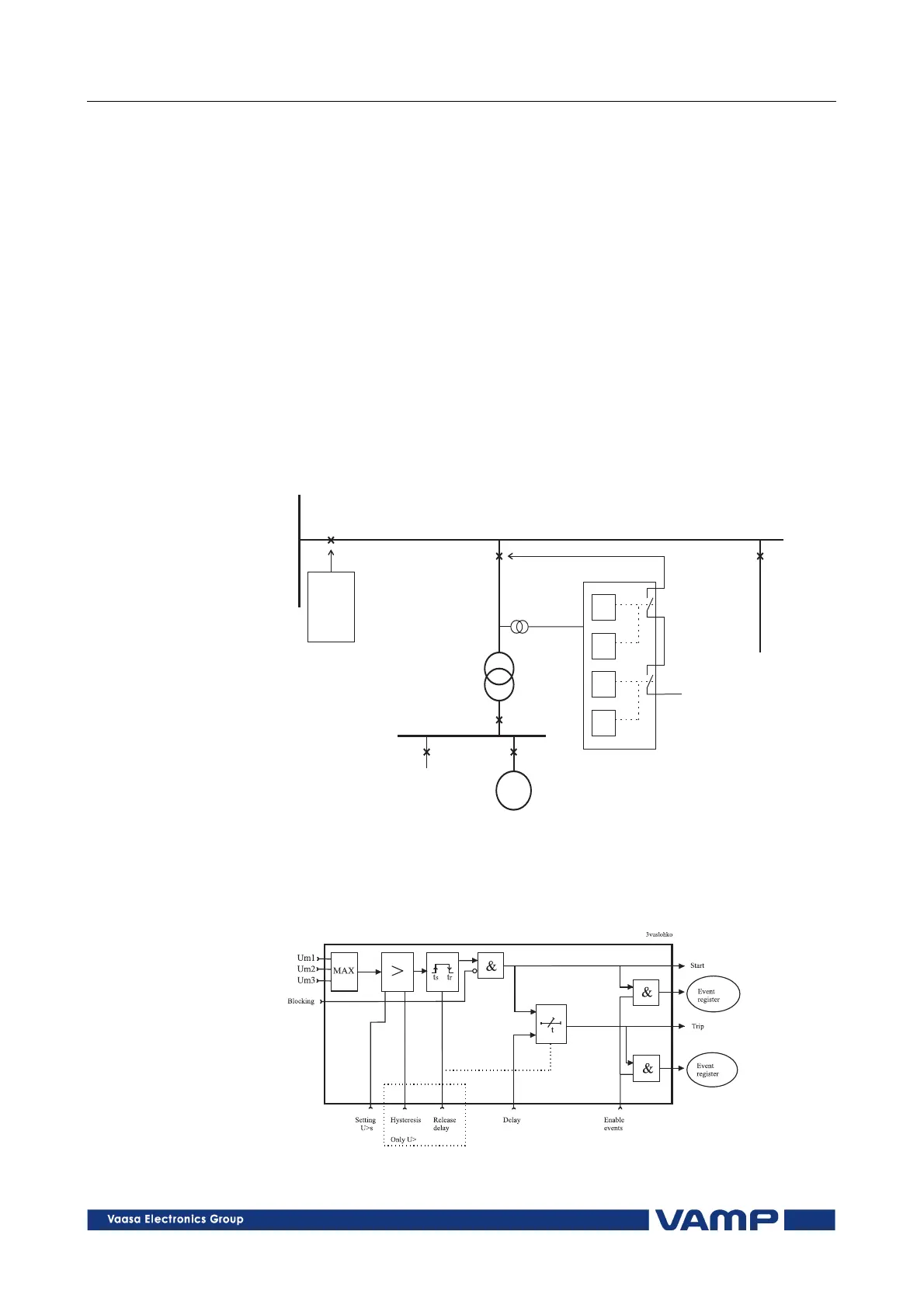
Another application for an extended release delay is to
disconnect a small generator from the network during the dead
time of an auto-reclose, see Figure 2.3.1-3. In a fault situation
breaker Q1 starts the auto-reclose sequence and opens. The
voltage relay at Q2 will also pick up any undervoltage or
residual overvoltage fault. If the voltage fault remains, Q2 will
also trip and reclosing cycle can continue. However, if the fault
is cleared by opening the Q1 and then Q2 will not trip the
voltage relay at Q2 has a long start release time. In most cases
the isolated load is too much for the generator to maintain the
frequency during this release time and the Q2 will be tripped
by a frequency stage and the possible past voltage fault.
Frequency fault or voltage fault in the network alone will not
trip Q2. An asynchronised connection of breaker Q1 to the
network is blocked with a synchro-check relay.
110kV
Auto
reclosing
with
synchro-
check
U<andsUo>stageshavea
releasedelayof10seconds.
110kV/10kV
GENERATOR
LOAD
LOAD
G
VAMP135
U<
f<
U>
0
f>
U U U
L1 L2 L3
+
LossofmainsapplicationusingVAMP135
START
START
TRIP
TRIP
Q1
Q2
Figure 2.3.1-1. The disconnection of a generator from the network during
the dead time of an auto-reclose cycle.
Figure 2.3.1-2 shows the functional block diagram of the
overvoltage unit’s U>, U>> and U>>> stages.
Figure 2.3.1-2. Block diagram of the three-phase overvoltage stages U>,
U>> and U>>>.