VAMP 135 Over-, under-, residual voltage and
frequency relay
Technical description
VAMP Ltd
26
VAMP 24h support phone : +358 (0)20 753 3264
VM135.EN008
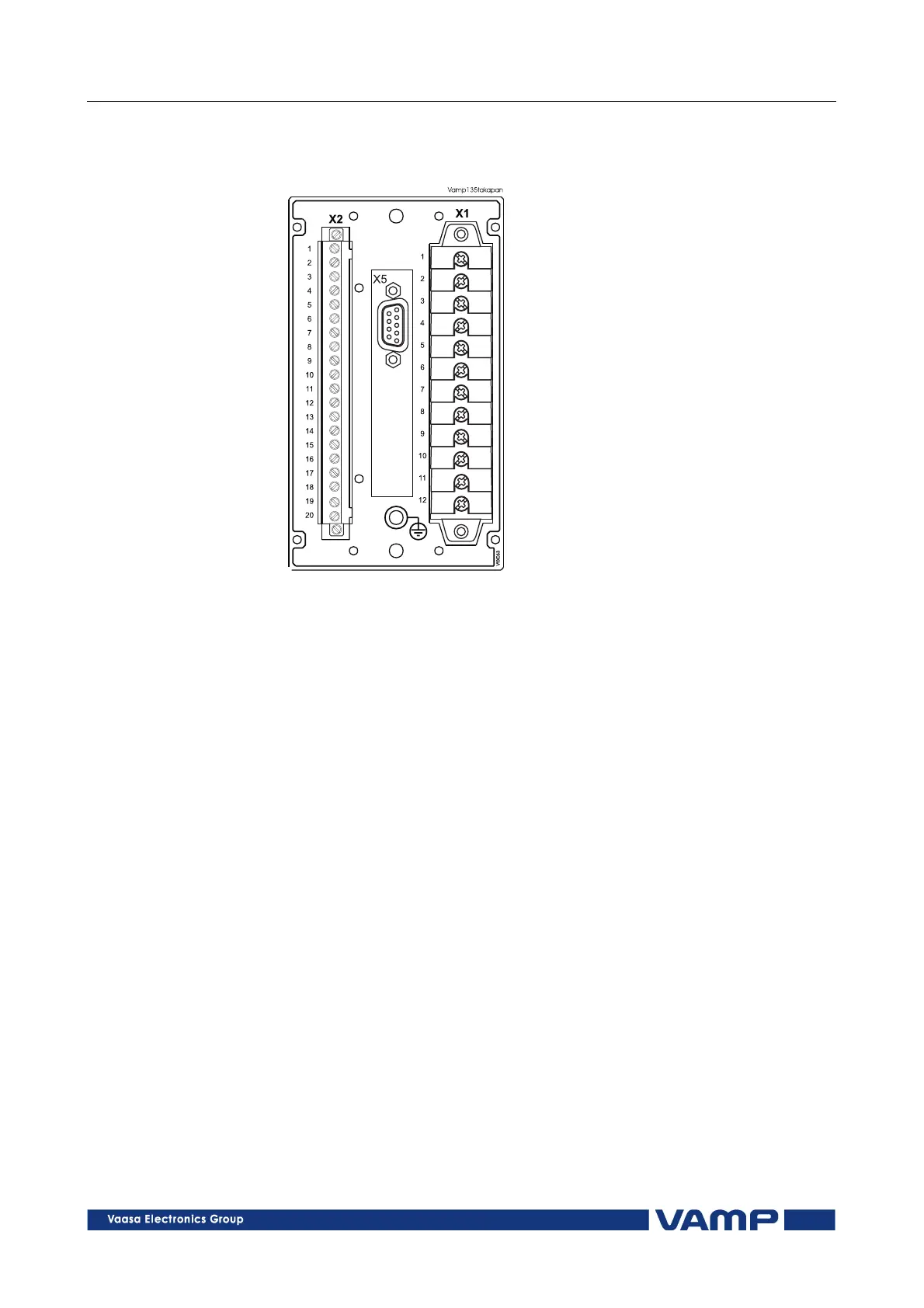
4. Connections
Figure 4-1. Connections on the rear panel of the VAMP 135 relay.
The VAMP 135 relay is connected to the protected object
through the following measuring and control connections:
• Phase voltage U
L1
or line voltage U
12
, terminals X1: 1 - 2
•
Phase voltage U
L2
or line voltage U
23
, terminals X1: 3 - 4
•
Phase voltage U
L3
or line voltage U
31
or residual voltage U
0
,
terminals X1: 5 – 6
4.1. Digital input
Further the relay can collect position information and alarm
signals via the digital input (terminals X2: 4 - 5) and store the
information in the event register. The digital input can also be
used to block protection stages under certain conditions.
Potential-free contacts for position indication must be available
in the protected application.
4.2. Auxiliary voltage
The external auxiliary voltage U
aux
(standard 40 to 265 V ac/dc
or 24 V dc, option B) for the relay is connected to the terminals
X1: 11 - 12, Figure 4-1.
Note:
Polarity of the auxiliary voltage U
aux
(24 V dc, option B):
+ = X1:11 and - = X1:12.