VAMP Ltd
Over-, under-, residual voltage and
frequency relay
Technical description
VAMP 135
VM135.EN008 VAMP 24h support phone : +358 (0)20 753 3264
23
VAMP135 V connection
2
1
U
mA
X2
5
4
BI
Measurement
functions
U ,U ,U
L1 L2 L3
U ,U ,U
12 23 31
U ,U ,U
0 1 2
-
+
2
4
6
19
12
1
3
5
20
11
17
16
14
13
9
12
8
11
7
10
X1
X1
X2
VAMP 135
T1
T2
A1
A2
A3
IF
Protectionfunction
~
U
12
U
23
U
0
f>,
f>>
f<,
f<<
Uo> Uo>>
U>>>
U<<<
U>
U>>
U< U<<
L1
L2
L3
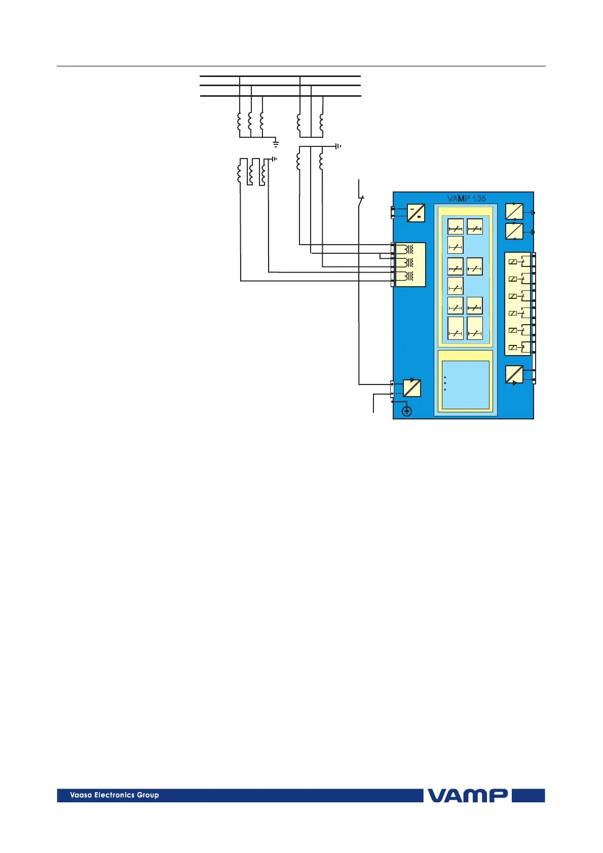
Figure 3.3-2 Three-phase overvoltage, undervoltage and residual voltage
protection of a feeder. Voltage transformers are V-connected. The voltage
measurement mode is set to “ 2Line+U
0
”
The relay only measures the line to line voltages U
12
and U
23
.
The line voltage U
31
is calculated from the other two. The
residual voltage is measured with an open-delta transformer.
The auxiliary contact of the voltage transformer’s contactor is
connected to the digital input for blocking of the undervoltage
stages.