WRM-10P/WRM-40 OPERATING INSTRUCTIONS
Table 3.0 Functional Descriptions of WRM-40 Controls and Indicators Con’t
Fig. 2
Index
Panel Markings
Functional Descriptions
10
HIGH VOLTAGE
PRESENT
Red LED indicator light. When lighted, this
indicator warns operators that there is a
possibility that voltage exists across the test
leads. Do not disconnect test leads when this
light is on. Failure to heed this warning can
result in shock and/or fatal injury to personnel.
11
V2
Voltage sensing input channel #2. Female Test
connector jacks for connecting voltage-sensing
test leads
4.0 PRETEST SETUP
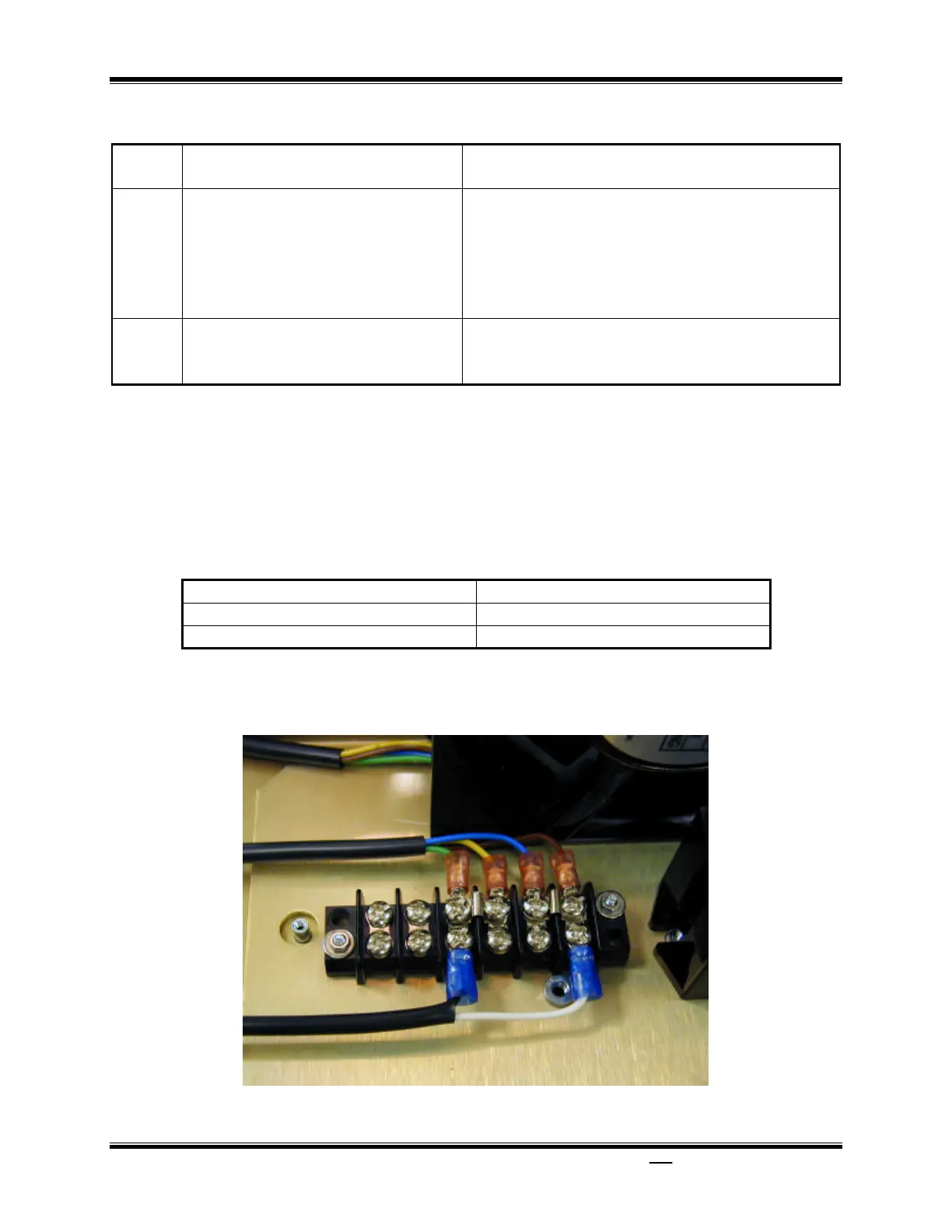
4.1 Operating Voltages
The WRM-10P/40 operating voltages are
selectable between 90-130Vac, 50/60Hz or
200-240, 50/60Hz. Voltage selection is set
by the placement of jumpers on the power
terminal block as listed in Table 4.0 below
and Figures 3.0 and 4.0.
Table 4.0 Voltage Selection
VOLTAGE SELECTION TERMINAL BLOCK JUMPERS
90-130Vac Brown to Blue & Yellow to Green
200-240Vac Blue to Yellow
Figure 3.0 90 to 130Vac Jumper Setting
 Loading...
