WRM-10P/WRM-40 OPERATING INSTRUCTIONS
6.0 OPERATING PROCEDURES
Before using the WRM-10P/40 for
measuring any resistance, operators should
review the WRM-10P/40 Menu Summary
found in Figure 5.0. WRM-10P/40
operations are simple, requiring the selection
of choices from the display menus and
responding to the displayed prompts.
However, first-time operators should review
Figure 5.0 to become familiar with the total
WRM-10P/40 operation and the logical
branching for various test options. More
experienced operators may use this figure as
a handy help and reference guide.
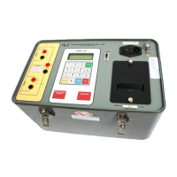
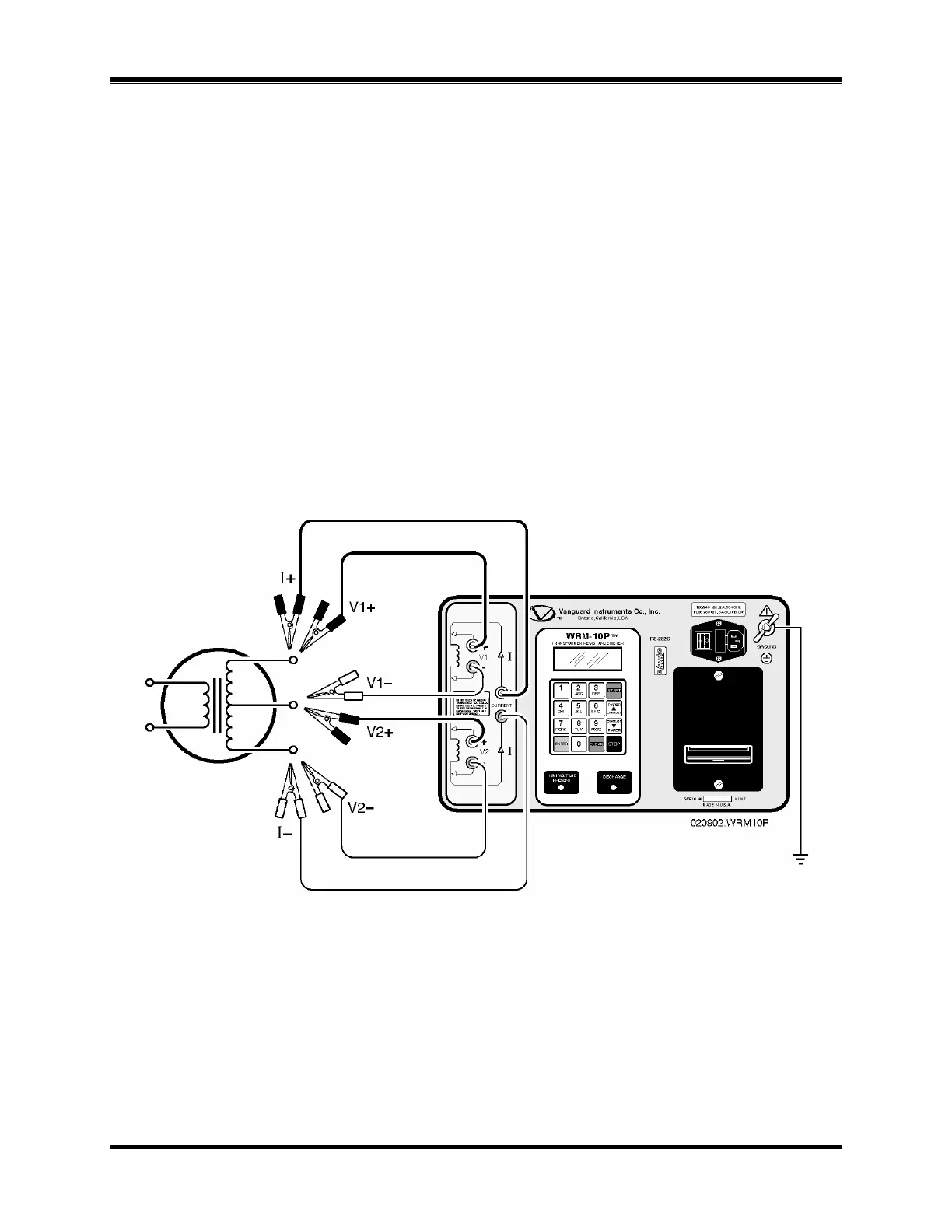
6.1 WRM-10P/40 Cable connection
A typical connecting diagram of the WRM-
10P/40 is shown in Figure 6.0 and
Figure 7.0.
WARNING
Do not touch or disconnect any test lead that is connected to a
transformer terminal while high current is being conducted during
a test. Failure to heed this warning can result in lethal electrical
shock to personnel and/or damage to the equipment.
Figure 6.0 Typical WRM-10P Connection Diagram
WARNING
Always disconnect test clips from transformer bushing after
discharge slowly to prevent any accidental flash-over.
 Loading...
