WRM-10P/WRM-40 OPERATING INSTRUCTIONS
6.2 General Procedures
a. Ground WRM-10P/40 to substation
ground (Item 6 in Figure 1.0, Item 5 in
Figure 2.0).
WARNING
Always connect the WRM-10P/40 to the
substation ground before connecting test
leads to any transformer bushing.
Failure to follow this procedure may
damage the WRM-10P/40.
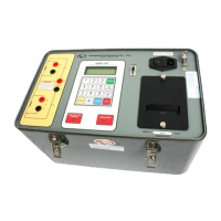
b. Plug the WRM-10P/40 power cable into a
power outlet.
c. Insert current-cable plugs and voltage-
sensing cable plugs into respective control-
panel jacks.
d. Attach test-cable clamps to the
transformer terminals for winding that is to
be measured.
e. Turn on the WRM-10P/40 power by
pressing “I” on the rocker switch.
f. Observe that after configuration data is
displayed briefly, the Start-Up menu
displays with selection options for “1. RUN
TEST”, “2. SETUP”, “3. USER
DIAGNOSTIC”.
6.3 Step-by-Step Procedures at Start-
Up Menu
6.3.1 START-UP Menu:
Observe that the Start-Up menu displays as
shown below:
a. Press key #1 to start a test. Press #2 to
select other options (i.e. enter record-
identification data, recall test results, etc.).
Press #3 to select Diagnostic functions.
6.3.2 Test Transformer Procedure
The following procedure shows the steps to
get a resistance reading from a device under
test.
a. To start a test, press key #1 (TEST
XFMR) from the Start-Up menu. The
following menu is displayed:
b. Press key #1 to use V1 and V2 test (dual
resistance test). Press key #2 to use only V1
test (single resistance test).
c. After the test mode is selected, a warning
menu is shown below:
This warning reminds the operator that the
next sequence of test steps will run current
through the test load.
d. Press the ENTER key and proceed to the
next step. The start test display appears:
Or
e. Press the START key to start the test. The
test-in progress display appears next:
DANGEROUS FLASH-OVER
MAY OCCUR IF CABLES
ARE DISCONNECTED!
2. SETUP 09:28:03
3. USER DIAG
2. V1 ONLY TEST
“START” TO RUN TEST
OR
“STOP” TO ABORT
“START” TO RUN TEST
OR
“STOP” TO ABORT
 Loading...
