WRM-10P/WRM-40 OPERATING INSTRUCTIONS
1.0 INTRODUCTION
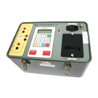
1.1 General Description
Vanguard Instruments Company’s WRM-
10P and WRM-40 are microprocessor-
controlled winding resistance meters. These
devices were designed specifically to
measure large transformer winding
resistance, motor winding resistance or
resistance of inductor devices. This manual
will address the WRM-10P and WRM-40 as
WRM-10P/40 as one device. Any
difference between the WRM-10P and
WRM-40 will be addressed separately.
The WRM-10P uses a 36-Volt/10 Amperes
Direct Current (DC) power supply. It is
capable of reading winding resistance
ranging from 1 micro-ohm to 2000 ohm.
The WRM-40 uses a 36-volt/40 amperes dc
power supply. It is capable of reading
resistance range from 1 micro-ohm to 500
ohm. Dual voltage sensing channels allow
the WRM10P/40 to read two resistance
values in the same test. To ensure operator
safety, the WRM-10P/40 automatically
discharges the energy stored in the
transformer at the end of each test.
TheWRM-10P/40 is rugged and field-
portable. It features simple, easy operation
and requires little training for first-time
users. A 16–key button allows the user to
control and enter transformer test data.
Resistance-readings are displayed on a 4-
line by 20-character LCD. A built-in
thermal printer produces test results on 2.5-
inch-wide thermal paper. Up to 63 records
(128 readings each) can be stored in the
FLASH EEPROM. The user can recall the
stored reports for printing or download the
test records to a personal computer (PC). A
RS-232C serial interface port is provided for
diagnostic testing and downloading test
records. A Windows based (Window 98/
2000/ NT/ XP) PC software is provided with
each WRM10P/40.
1.2 Functional Description
The WRM-10P/40’s operation is based on
the electrical relationships described by
Ohm’s law: R=V/I, where I is a known
current and V is the DC voltage measured
across the unknown resistance. The value of
the unknown resistance under test is the
direct function of the measured voltage
divided by the current which is calculated
by the microprocessor. Resistance readings
are then displayed on a back-lighted 4 line
by 20 character LCD.
A special current source allows the WRM-
10P to output up to 10 Ampere of test
current or 40A test current for the WRM-40.
Test current is automatically adjusted
depending upon the load resistance. The
current source circuit is thermally protected.
A built-in discharge circuit automatically
discharges the energy stored in the
transformer at the end of each test.
1.3 Furnished Accessories
The WRM-10P/40 is shipped with six 50-
foot test cables with “quick disconnect” type
test plugs on the unit end and battery-type
clamps at the test load. One power cord,
one ground cable and a cable-carrying bag
are also included.
 Loading...
