WRM-10P/WRM-40 OPERATING INSTRUCTIONS
Table of Figures
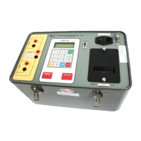
Figure 1.0 WRM-10P Controls and Indicators..........................................................................6
Figure 2.0 WRM-40 Controls and Indicators............................................................................9
Figure 3.0 90 to 130Vac Jumper Setting .................................................................................11
Figure 4.0 210 to 240Vac Jumper Setting ...............................................................................12
Figure 5.0 WRM-10P/40 Menu Summary ..............................................................................13
Figure 6.0 Typical WRM-10P Connection Diagram ...............................................................14
Figure 7.0 Typical WRM-40 Connection Diagram .................................................................18
Figure 8.0 Typical Dual Reading Test Report Printout............................................................22
Figure 9.0 Typical Single Reading Test Report Printout .........................................................22
Figure 10.0 Typical Record Directory Printout.........................................................................27
 Loading...
