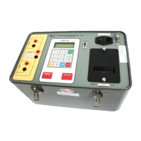
WRM-10P/WRM-40 OPERATING INSTRUCTIONS
b. Pressing key #4 (NEXT PAGE) and the
following menu below appears:
c. Press key # 1 (COMPUTER CONTROL)
and go to the next step. The display below
appears:
d. Pressing the STOP key terminates the
computer control, at which time the Start-Up
menu displays, ending this step sequence.
6.4.7 Setting Date and Time
a. The date and time set begins by pressing
key #2 from the Start-Up menu. The display
below is now shown on the WRM-10P/40
LCD:
b. Press key # 4 (NEXT PAGE). The menu
below appears:
c. Press key # 2 (SET TIME) and go to the
next step. The next display appears:
d. Enter the date and time, which appear in
the dashed-line areas, then press the ENTER
key to set the calendar and clock and to
return to the Start-Up menu. This ends the
“Set Time” step sequence.
6.4.8 Voltage Regulator Test
Note
This test verifies that a regulating
switch in a primary-voltage tap
regulator changes contacts through its
selection range with no break in the
circuit (i.e., it checks the tap switch’s
make-before-break). This test is
important because, in actual use, any
break in current in a regulating tap
switch generates large reactive voltage
spikes that are hazardous and exceed
the switch’s voltage ratings, thus
causing irreparable damage.
By connecting the WRM-10P/40
continuity test input across the
switching input and running the
regulator switch through all the
contacts in it’s range, any breaks in
continuity caused by faulty tap
switching will be detected.
To run the Voltage-Regulator test, perform
the following step-by-step sequence, starting
with the Start Up menu (see below):
2. REVIEW RECORD
3. RESTORE RECORD
4. NEXT PAGE
2. SET TIME
3. VOLTAGE REG TEST
MM-DD-YY HH:MM:SS
2. SETUP 12:21:01
3. USER DIAG
2. SET TIME
3. VOLTAGE REG TEST
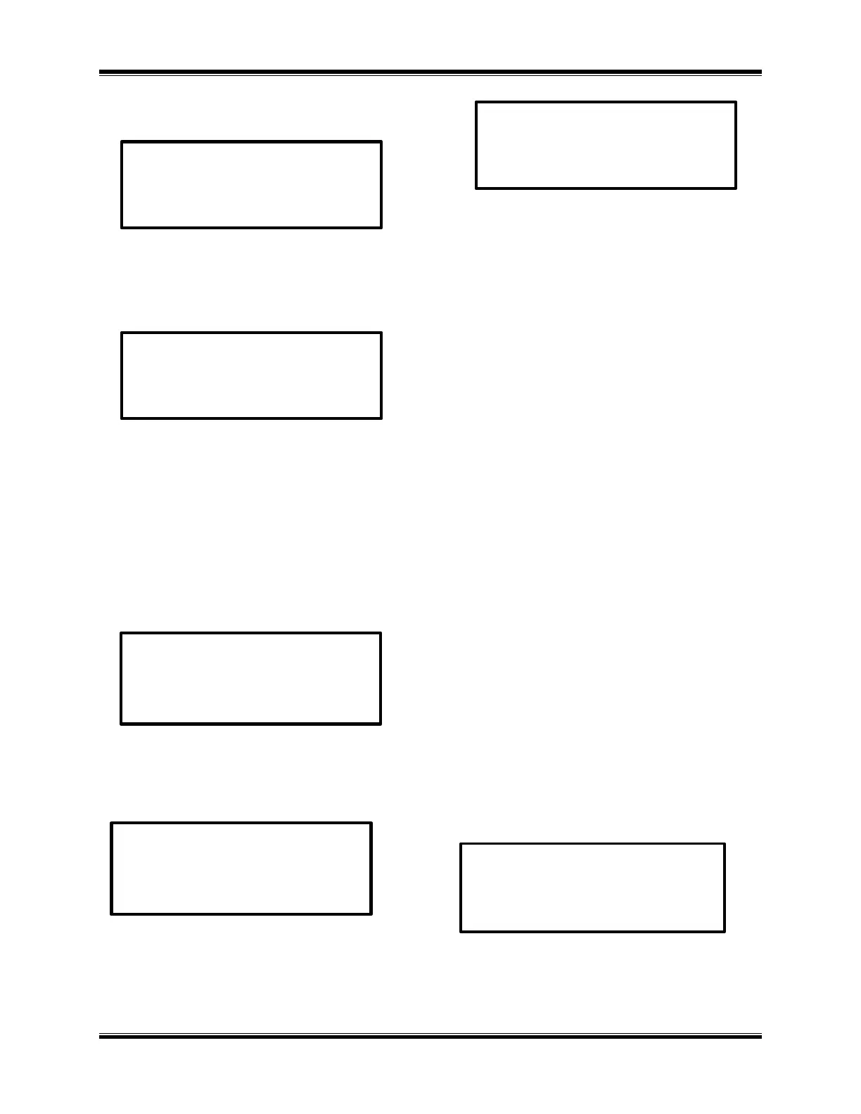 Loading...
