2-3
2 System Description System Parts Identification
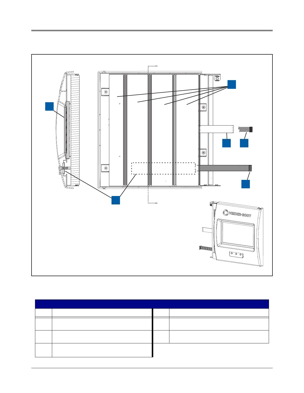
Figure 2-3. Display Door Assembly
Legend For Figure 2-3
Item Description Item Description
1 Touch screen display assembly 4 Cable to Ack Switch Panel connector on CPU board
(item 16 in Figure 2-11)
2 Input Module Connection Labels 5 Cable to LED Backlight connector on CPU board (item
11 in Figure 2-11)
3 Cable to Data Display connector on CPU board (item 6
in Figure 2-11). Data Display is an option.
6 Front panel sysem status LED board assembly
A
A
6
5
3 4
1
Section A-A
2