2 System Description System Parts Identification
2-8
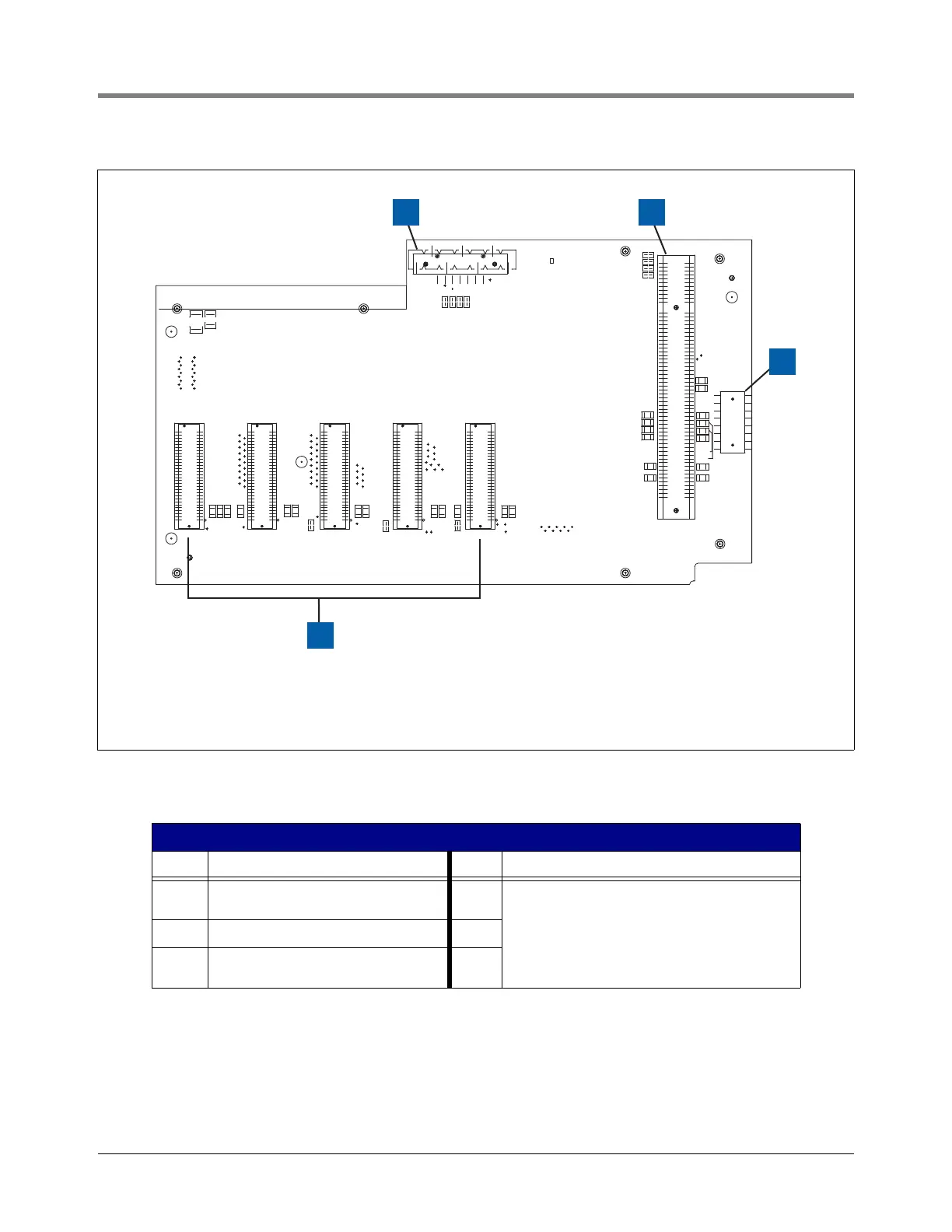
Figure 2-8. Comm Backplane Board
Legend For Figure 2-8
Item Description Item Description
1 J2 connector connects to J4 on Power
Supply board
4 J4 - J8 connectors for optional Comm modules
(Comm modules keyed for certain slots)
See Figure 2-9 for user selectable Comm Modules.
See Table 2-1 for permissible slots/ports for user
selectable Comm Modules
See Figure 2-10 for fixed Comm Modules.
2 J3 connector for CPU board
3 J9 connector connects to J1 connector on
I/O Backplane board
B62
B1
B12
A62
A12
A1
2
59
60
2
59
60
2
59
60
2
59
60
2
59
60
30
30
29
29
30
29
30
29
30
29
JJL 290807
REV - A
J2
A37
A28
1
B37
B28
R27
VRBUS+
SLOT 1 SLOT 2 SLOT 3
SLOT 4
SLOT 5
J3
J9
R2
J4 J6
J7
J5
J8
FD2
FD1
R17
R15
R16
R21
R29
R18
R22
C10
M81
R25
C9
R20
R24
C8
R19
M82
R23
R6
R5
R4
R3
R14
R13
R12
R10
R11
BACKPLANE
TO I/O
GND
GND
+24V
+24V
NO COMPONENTS OR TRACES ABOVE THIS LINE
FD3
R30
C12
J1
332881-001 Rev A
BD Group - Comm.Backplane board
TLS-450 console
POWER STATUS
RELAY CONTROL LINE
C1
C2
C3
C11
+24V
+24V
GND
GND
GND
C4
R1
C7
C5
C6
R7
R9
R8
VRBUS-
VRBUS_RST
N/C
FD4
1 2
3
consoles\450\918-9.eps
4