When the drive voltage is at a positive value, the drive is turned on, and at a negative
value, the drive is turned off, so use the AC gear to measure it.
◼ Measurement of normal voltage points during operation:
The UTP, VTP, and WTP voltages are generated by the VDR, if there is a problem there,
the drive voltage generated by the switching power supply is faulty Problems.
Measure the voltage of the drive signal on the control board when it is not in operation
(DC phase).
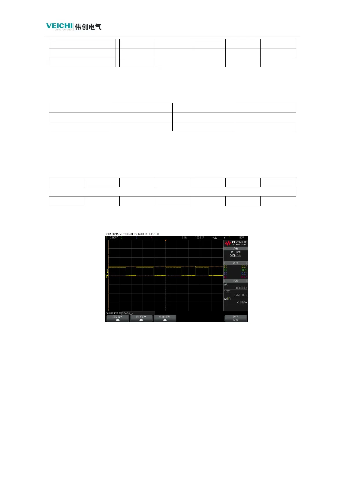
Waveforms of one of the drive signals and GND outputs during operation: as follows
(if the output waveforms are abnormal, the control board is abnormal)
Measure the voltage of each drive signal and GND is about 11.5v when running with
ACgear.
◼ Use two ripple probes (pay attention to isolation) to connect to the upper and lower arm
drivers of the same phase (directly soldered to the IGBT pins), power up and run the
whole machine, and test the driving waveforms. (If there is no waveform, the module
may be damaged, or the UH, UL, VH, VL, WH, WL provided on the control board may
be defective.).