AC310 Universal AC Drive Service Manual
6
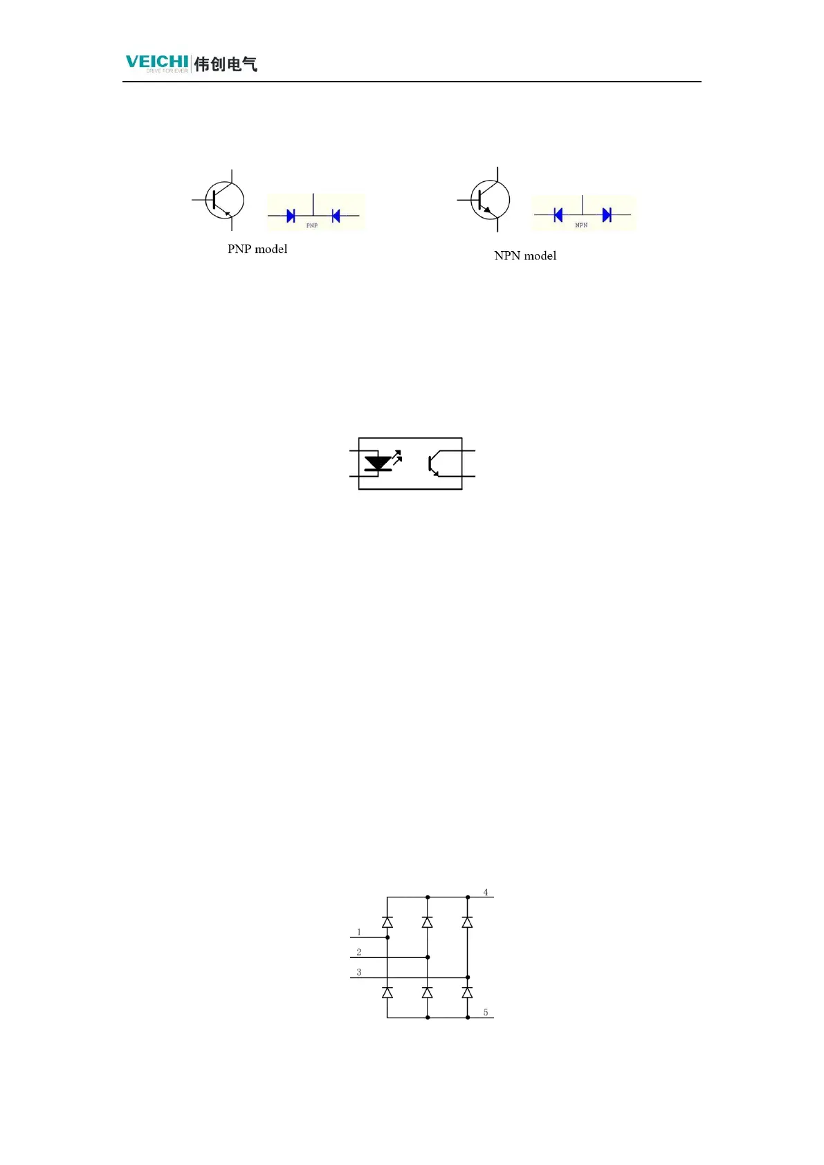
drop of about 0.7V is a silicon tube, and the one with a voltage drop of about 0.3V
is a germanium tube.
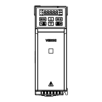
1.2.3 Optocoupler
The circuit principle and symbols of commonly used optocouplers are shown in
the following figure:
One side is a light-emitting diode, the voltage drop is about 1V, the other side is a
transistor, some only lead out c, e, measurement of forward and reverse are cut off, if
all three legs lead out, the measurement characteristics are the same as the above
transistor (mostly NPN tubes). When using a multimeter to make the diode forward
conduction, at this time with another multimeter to measure the transistor c to e
conduction voltage drop of about 0.15V; disconnect the diode connected to the
multimeter, the transistor c to e cutoff, indicating that the optocoupler is good.
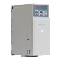
1.2.4 Static Measurements of Rectifier Bridges
Three-phase bridge rectifier electrical schematic diagram, points 1, 2 and 3 are RST
inputs, points 4 and 5 are P and N. Measurement method is the same as that of a normal
diode.