AC310 Universal AC Drive Service Manual
7
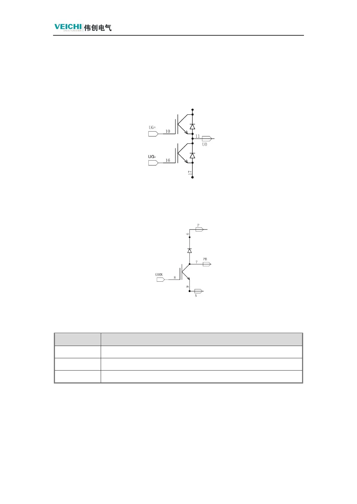
1.2.5 Static Measurements of AC Drive Continuity Diodes
Schematic diagram of the AC drive unit, the measurement method is the same as ordinary
diodes. Measurement of the IGBT diode to determine the damage. Just put a meter pen into the
U, V, W output, a meter pen on the P or N, you can measure the good or bad.
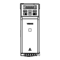
1.2.6 Static Measurement of Brake Units
Brake Unit Schematic
GBRK is the braking signal in the diagram. Connect a braking resistor between
terminals P and PB, refer to the instruction manual for specifications.