Chapter 3: Installation (Top of Floor)
Modes of Operation
(2/01) 3-5
Modes of Operation
Analog Mode
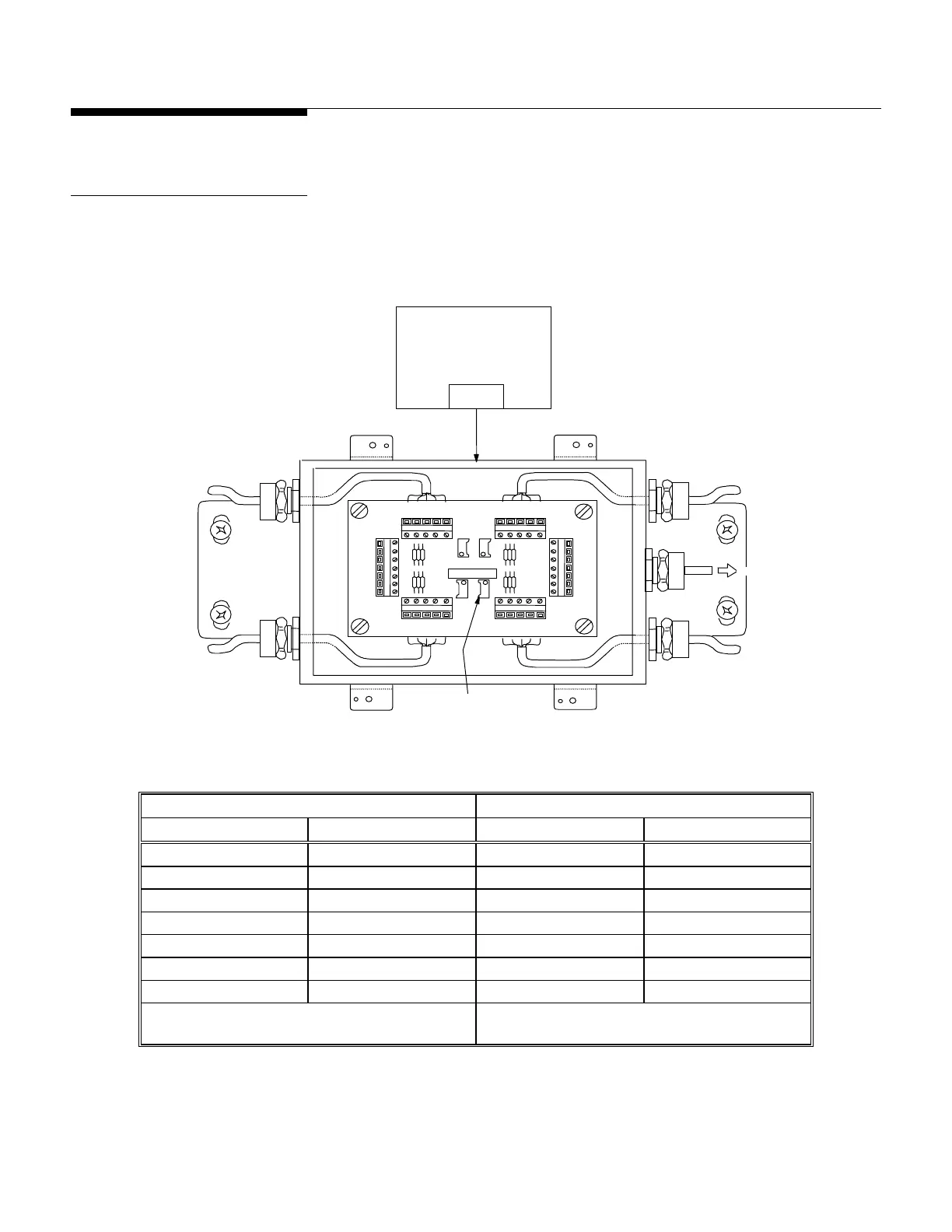
A Model 2158 floor scale is used with an analog junction box for summing the load cell
outputs. Only analog-compatible indicators work with the analog junction box. See
Figure 3-6 and Table 3-1 for the correct cable connection.
Figure 3-6: Analog Junction Box Detail
Load Cell Wiring Instrument Cable Wiring*
Function Color Function Color
+Excitation Green +Excitation White
+Sense Not Used +Sense Yellow
+Signal White +Signal Green
Shield Yellow Shield Orange
-Signal Red -Signal Black
-Sense Not Used -Sense Red
-Excitation Black -Excitation Blue
*(Based on METTLER TOLEDO
Cable Number 510624370)
Table 3-1: Analog Junction Box Wiring Codes
Note: Do not cut load cell
cables. Cutting a cable will
affect compensation and void
the warranty.
Note: Turn all potentiometers fully
clockwise prior to calibration.
L
2
L
1
L
4
L
I
N
P
U
T
U
X
+EXE
+SEN
+SIG
SHLD
-SIG
-SEN
-EXE
+EXE
+SEN
+SIG
SHLD
-SIG
-SEN
-EXE
+EXE
+SIG
SHLD
-SIG
-EXE
+EXE
+SIG
SHLD
-SIG
-EXE
+EXE
+SIG
SHLD
-SIG
-EXE
+EXE
+SIG
SHLD
-SIG
-EXE
Load Cell Orientation
(Top View of Platform)
To LC2
LC4
LC3LC1
To LC1
To LC3
To LC4
To Indicator
Individual Load Cell
Trimmin
Potentiometer
LC2
ANALOG JBOX
 Loading...